Quick connector

a connector and connector technology, applied in the direction of couplings, combustion air/fuel air treatment, feed systems, etc., can solve the problems of generating positive collision noise, unable to secure affecting the smooth snap-closing motion of the engaging arms, etc., to achieve smooth snap-closing motion, positive collision noise, and positive collision noise

Active Publication Date: 2006-09-28
SUMITOMO RIKO CO LTD
View PDF20 Cites 12 Cited by
  • Summary
  • Abstract
  • Description
  • Claims
  • Application Information

AI Technical Summary

Benefits of technology

[0011] In order to achieve a foregoing object, there is provided a novel quick connector for connecting a pipe and a hose. The quick connector for connecting the pipe and the hose comprises a tubular connector housing that is provided at one axial end with a hose connector portion for being connected to the hose and at the other axial end with a pair of diametrically opposed engaging slits, a wire retainer of U-shape or generally U-shape having a pair of engaging arms. The wire retainer is mounted to the other axial end of the connector housing in such a manner that the pair of the engaging arms clip the connector housing while extending through a respective one of the engaging slits. The engaging arms of the wire retainer project through the respective one of the engagement slits into the connector housing. The engaging arms are configured to be brought in opening motion with the engaging arms being pushed by an annular engaging projection formed on an inserting end of the pipe that is inserted into the connector housing, and then in closing motion so as to engage with the annular engaging projection. Each of the engaging slits has a width larger than a diameter of the engaging arm in order to generate a collision noise or collision sound by collision between the engaging arm and the connector housing or the pipe upon completion of the closing motion of the engaging arms. Generation of the collision noise allows an operator to verify completion of the closing motion of the engaging arms, namely complete connection between the pipe and the connector. The engaging slit with the width larger than the diameter of the engaging arm facilitates smooth snap-closing motion of the engaging arms. Here, when the wire retainer is made of metal and the connector housing and / or the pipe are also made of metal, a positive collision noise can be expected to be generated. For the connector where the engaging arms collides or bumps against the connector housing, for example, circumferential end portions of the engaging slits upon completion of the closing motion of the engaging arms, the connector housing may be made of metal. For the connector where the engaging arms collides or bumps against an outer periphery of the inserting end portion of the pipe (an outer periphery of the inserting end portion except for the annular engaging projection) upon completion of the closing motion thereof, the pipe may be made of metal. And the width of each of the engaging slits can be designed small (for example, minimum) an extent that the positive collision noise can be generated, and thereby stable connectability of the pipe with the connector can remain undisturbed.
[0013] It is effective that the inserting end portion of the pipe is configured so as to be inserted in the connector housing, until an annular surface of the annular engaging projection at the other axial end conforms to or beyond one axial end extremity of the engaging slit. By virtue of this configuration, snap-closing motion of the engaging arms is prevented from being disturbed by resistance to sliding movement of the engaging arms that is provided by the annular surface of the annular engaging projection at the other axial end.
[0014] In the quick connector according to the present invention, each of the engaging arms may have a leading end portion that is bent over or inclined radially inward to define an engaging portion. And the wire retainer may be configured to move to a pull-out position where a leading end of the engaging portion engages a stop portion of the connector housing in a pull-out direction, while sliding the leading end of the engaging portion over an outer peripheral surface of the connector housing so as to gradually open the engaging arms. Further, the engaging portion may be formed not to allow the engaging arms of the wire retainer that reaches to the pull-out position to open so as to be disengaged from the annular engaging projection of the pipe, or may be formed to maintain engaging relation of the engaging arms of the wire retainer that reaches to the pull-out position with the annular engaging projection of the pipe. That is, the wire retainer may be configured such that the engaging relation of the engaging arms with the annular engaging projection of the pipe is maintained while the wire retainer is moved from the mounted position to the pull-out position. For example, the engaging portions engage with the outer peripheral surface of the connector housing, more specifically, the outer surfaces of the connector housing toward the mounting direction with respect to a center in the mounting and pull-out direction, in the pull-out direction and thereby the wire retainer can be maintained in the mounted position. According to one aspect of the present invention, since the wire retainer is constantly kept in a state that the engaging arms do not open so as to be disengaged from the annular engaging projection, the pipe can be effectively prevented from being disconnected from the connector.
[0015] In case of providing an axial portion on the leading end portion of the engaging portion that is bent over in the axial direction of the connector housing in view of safety, etc., the axial portion may be configured to engage with the stop portion of the connector housing in the pull-out direction. This configuration can secure a good stop effect with respect to the pipe.
[0018] As described above, a quick connector according to the present invention facilitates smooth connecting work for piping since engaging arms generate discriminant sound or sound signal that allows an operator easily verify complete connection of the pipe with the connector. Furthermore, according to one aspect of the present invention, it becomes possible to provide quick connector also having a configuration free from fear that engagement relation between the pipe and the connector is cancelled during use.

Problems solved by technology

Here, when the wire retainer is made of metal and the connector housing and / or the pipe are also made of metal, a positive collision noise can be expected to be generated.
When each of the engaging slits has the width smaller than 1.1 times the diameter of the engaging arm, there is fear that smooth snap-closing motion of the engaging arms cannot be secured.
When each of the engaging slits has the width larger than 1.3 times the diameter of the engaging arm, there is fear that the engaging arms have too large play or clearance relative to the engaging slits and thereby stable connectablility of the pipe with the connector is disturbed.

Method used


Image

  • Quick connector
  • Quick connector
  • Quick connector

Examples


Embodiment Construction

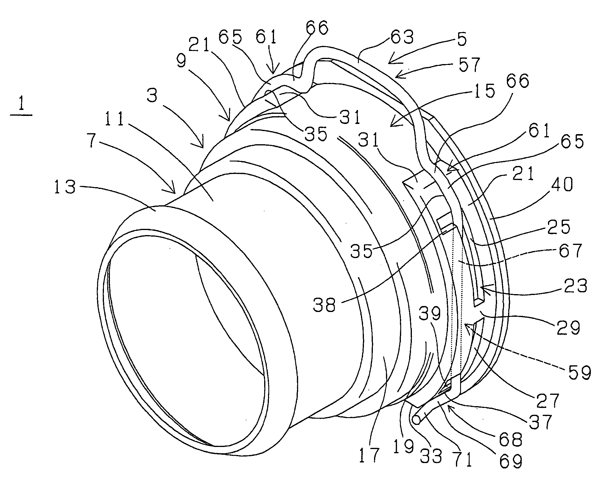
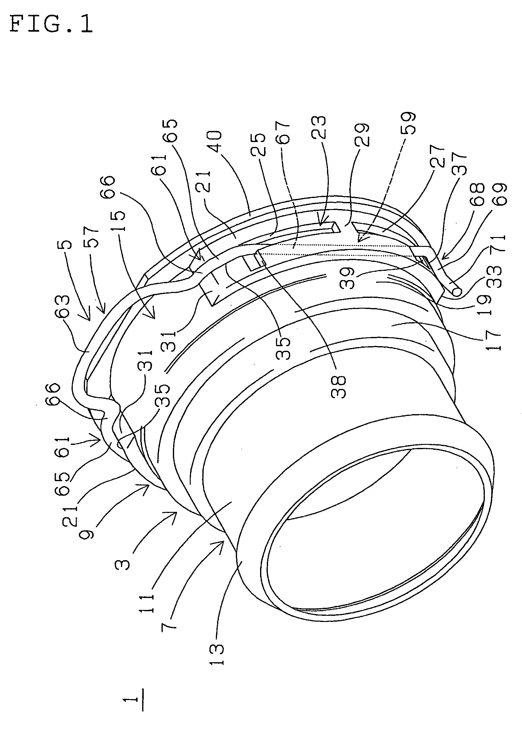
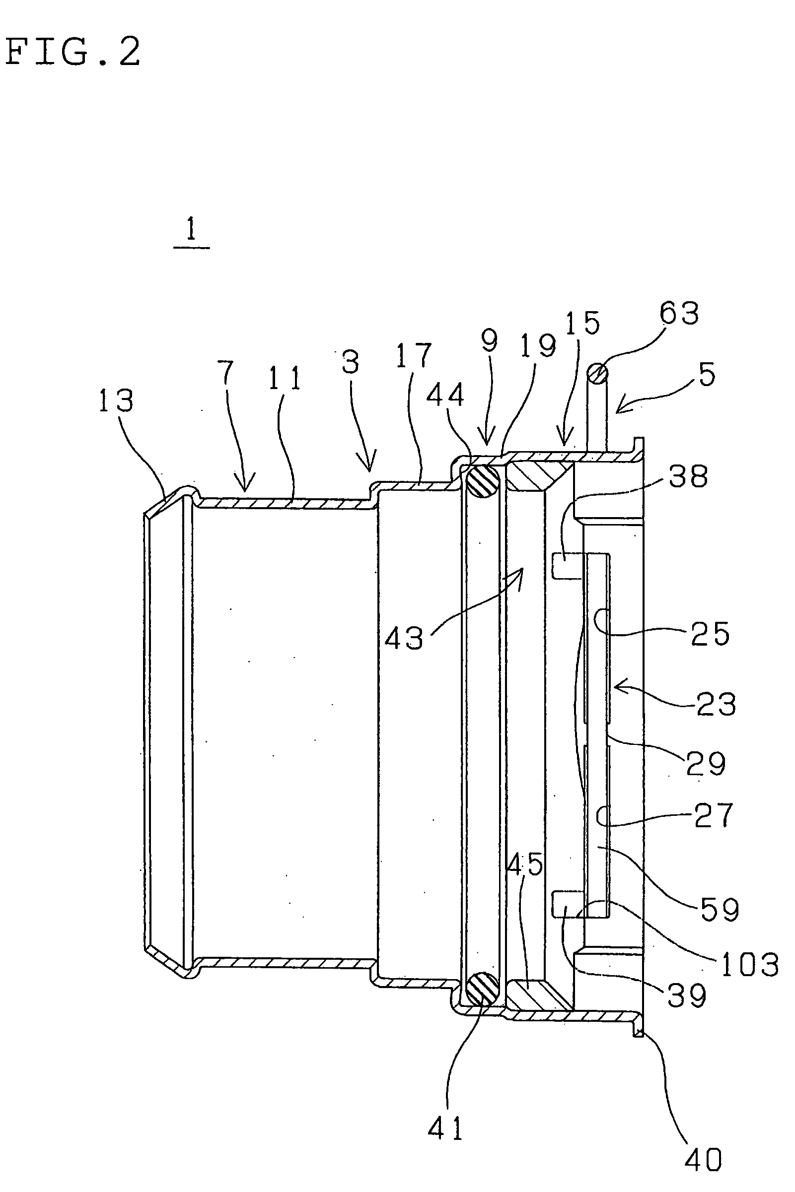
[0036] A first quick connector 1 shown in FIGS. 1 to 5 is adapted, for example, for assembly in air supply and exhaust piping of an automobile. As well understood specifically from FIGS. 1 to 3, the first quick connector 1 comprises a tubular connector housing 3 which is thin-walled, a first wire retainer 5 of U-shape or generally of U-shape mounted on or to the connector housing 3. The connector housing 3, for example, made of metal, has a cylindrical hose connector portion 7 (hose connector portion) at one axial end of the connector housing 3 (namely on one side in a direction of an axis thereof) and a generally cylindrical pipe inserting portion 9 at the other axial end of the connector housing 3 (namely on the other side in a direction of an axis thereof) as a unit. The connector housing 3 is formed large in diameter and relatively short in axial length to connect a hose of large diameter and a pipe of large diameter.

[0037] The hose connector portion 7 includes a cylindrical co...


PUM


Abstract

A quick connector is provided with a connector housing and a wire retainer. The connector housing has a retainer mounting portion which is formed with engagement slits. The wire retainer is mounted on the retainer mounting portion such that engaging arms enter the engagement slits and project in the retainer mounting portion. Each of the engaging slits has a width larger than a diameter of the engaging arm in order to generate a collision noise by collision between the engaging arm and the connector housing or the pipe upon completion of closing motion of the engaging arms.

Description

BACKGROUND OF THE INVENTION [0001] 1. Field of the Invention [0002] The present invention relates to a quick connector, for example, to be adapted for assembly in piping of an automobile. [0003] 2. Description of the Related Art [0004] In a fluid piping system where a pipe and a hose are connected, a connector is used for connecting the pipe and the hose. In such piping system, the connector has a tubular connector housing including a connector portion at one axial end to be connected to the hose. And, for example, the pipe includes an inserting end portion on an inserting end thereof wherein an annular engagement projection is formed on and around an outer peripheral surface, retainer means is provided at the other axial end of the connector housing for snap-engagement, and thereby the connector is configured as quick connection type. Then, the inserting end portion of the pipe is inserted into an opening on an end of the connector housing so that the annular engagement projection ...

Claims


Application Information

Patent Timeline
Patent Type & Authority Applications(United States)
IPC IPC(8): F16L39/00
CPCF16L37/088F16L37/144F02M35/10144F16L37/0885
Inventor MORI, HIROYOSHINISHIMURA, MOTOHIDESOUJI, TETSUYA
Owner SUMITOMO RIKO CO LTD
Why Eureka
Try Eureka