
Image forming apparatus

a technology of image forming apparatus and forming tube, which is applied in the direction of electrographic process apparatus, instruments, optics, etc., can solve the problems of reducing the quality of the image, reducing the image quality, so as to reduce the degradation of the image quality

Active Publication Date: 2006-10-05
CANON KK
View PDF6 Cites 33 Cited by
  • Summary
  • Abstract
  • Description
  • Claims
  • Application Information

AI Technical Summary

Benefits of technology

The invention aims to prevent image quality degradation caused by the conveyance condition of a recording material after it is fixed in a fixing device. This is achieved by controlling the recording material conveyance speed of the fixing device so as to form a loop of the recording material between the transfer portion and the fixing device in two modes: a first mode that keeps the loop within a certain range and a second mode that keeps the loop smaller than the first range. This ensures that the recording material is always within the loop, regardless of its position in the apparatus. After the leading end of the recording material reaches the fixing device, the controlling device switches to the first mode to keep the loop within the certain range, and before the rear end of the recording material reaches the transfer portion, the controlling device switches to the second mode to keep the loop smaller than the first range. This ensures that the recording material is always within the loop, regardless of its position in the apparatus, and prevents image quality degradation caused by the conveyance condition of the recording material.

Problems solved by technology

In this manner, the difference in recording material conveyance speed between the fixing roller pair 105 and the transfer roller pair 103 has possibly induced degradation of an image quality.
Such a scrape on the conveyance guide 120 has generated the blur of the image during the transfer of the image, thereby possibly inducing the degradation of the image quality.
Such a bounce of the recording material P has caused the blur of the image, thereby possibly inducing the degradation of the image quality.
However, the configuration, in which the level of the loop of the recording material is reduced by switching the speed, has raised a problem, as described below.
Therefore, in the case where the rear end passes through the transfer portion before the loop becomes satisfactorily small, the bounce of the rear end cannot be securely prevented.
In contrast, in the case where the rear end passes through the transfer portion after there is no loop of the recording material, a fixing roller pair has applied a tension to the recording material since the conveyance force of the fixing roller pair is normally greater than that at the transfer portion, thereby possibly inducing a deficient transfer at the transfer portion.
As described above, the prior art has experienced the problem that the rear end of the recording material cannot be stably prevented from bouncing up.

Method used


Image

  • Image forming apparatus
  • Image forming apparatus
  • Image forming apparatus

Examples


first embodiment

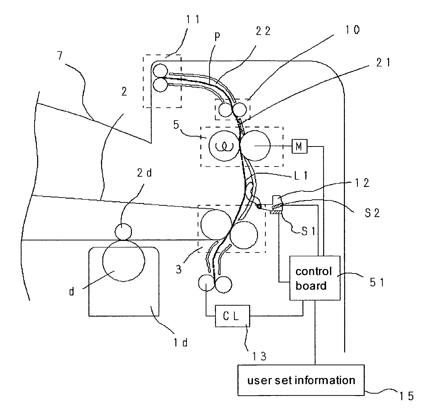
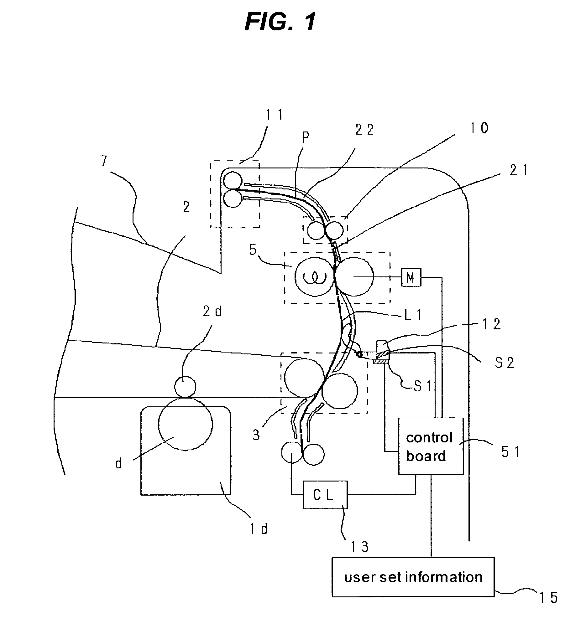
[0032] A description will be given below of an image forming apparatus according to the embodiment of the invention in reference to the drawings. FIG. 1 is a cross-sectional view showing the schematic configuration of essential parts of an image forming apparatus according to the embodiment of the invention; FIG. 2 is a timing chart illustrating the operation of the image forming apparatus according to the embodiment of the invention; FIG. 3 is a block diagram illustrating the image forming apparatus according to the embodiment of the invention; and FIG. 9 is a cross-sectional view showing the general configuration of the image forming apparatus according to the embodiment of the invention.

[0033] Explanation will be first made on the schematic configuration of the entire image forming apparatus, and thereafter, on selection of a loop detecting sensor in response to information on a recording material and a loop keeping control for the recording material in response to a detection s...

second embodiment

[0078] A description will be given below of an image forming apparatus according to a second embodiment of the invention in reference to the drawings. FIG. 7 is a block diagram illustrating a control system of the image forming apparatus according to the second embodiment of the invention, and FIG. 8 is a table illustrating constant tables stored in a memory in the image forming apparatus according to the second embodiment of the invention.

[0079] The present embodiment is the same in configuration as the above-described first embodiment, but is different in that information on a recording material includes information on a rigidity of a recording material and environmental information. Moreover, a controlling device is designed in such a manner as to select a loop detecting device for detecting a loop in accordance with the information on the rigidity of the recording material and the environmental information out of a plurality of loop detecting devices. Incidentally, the configur...


PUM


Abstract

An image forming apparatus includes a plurality of loop detecting sensors which detect various levels of loops formed on a recording material; and a controlling device which selects a specific one out of the loop sensors in accordance with information on the recording material, and then, switches a conveyance speed of a fixing roller pair in response to a detection signal output from the specific sensor, so as to control in such a manner as to keep the loop of the recording material within a constant range, the controlling device selecting the loop detecting sensor for detecting a loop of a level in accordance with the information on the recording material, so as to perform a loop keeping control for the recording material in response to the detection signal output from the selected loop detecting sensor.

Description

BACKGROUND OF THE INVENTION [0001] 1. Field of the Invention [0002] The present invention relates to an image forming apparatus of an electrophotographic type, in which a unfixed image is transferred onto a recording material at a transfer portion, and then, the unfixed image is fixed onto the recording material in a fixing device. [0003] 2. Description of the Related Art [0004] In a conventional image forming apparatus of an electrophotographic type, a unfixed image borne by an intermediate transfer belt 102 has been transferred onto a recording material P by a transfer roller pair 103, to be then fixed onto the recording material P by a fixing roller pair 105, and thereafter, the recording material having the image fixed thereto has been discharged to a discharge tray 107 disposed outside of the apparatus by a discharge roller pair 111, as shown in FIG. 11. [0005] The fixing roller pair 105 has been adapted to heat-fix the unfixed image onto the recording material. Heat temporaril...

Claims


Application Information

Patent Timeline
Patent Type & Authority Applications(United States)
IPC IPC(8): G03G15/20
CPCG03G15/657G03G2215/00738G03G2215/2045G03G15/2028G03G2215/00945
Inventor KOSHIDA, KOHEI
Owner CANON KK
Learn More