
Dual USB port device

a usb port and dual-port technology, applied in the direction of instruments, electric digital data processing, etc., can solve the problems of port and “standard” b port being extinct, peripheral devices which use, and not being able to establish usb connection to digital cameras

Inactive Publication Date: 2006-10-05
SYMBOL TECH INC
View PDF7 Cites 17 Cited by
  • Summary
  • Abstract
  • Description
  • Claims
  • Application Information

AI Technical Summary

Benefits of technology

"The present invention is about a system that includes two devices connected by a USB cable. The cable has two USB connectors and a voltage detector. The first device has a USB port and a voltage detector, while the second device has a USB port and a voltage detector. The first device detects the voltage at the second port and switches between a host state and a client state based on the detected voltage. The technical effect of this invention is to provide a convenient and flexible way to connect two devices using a USB cable."

Problems solved by technology

For example, a PDA could not have established the USB connection to the digital camera.
While the mini-AB port overcomes the problem of the conventional systems, the peripheral devices which utilize the “standard” A port and the “standard” B port may become extinct if the mini-AB port becomes the standard on such devices.
This may represent significant costs in new hardware purchases, as well as training and maintenance for the new hardware.

Method used


Image

  • Dual USB port device
  • Dual USB port device
  • Dual USB port device

Examples


Embodiment Construction

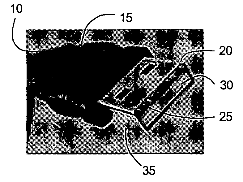
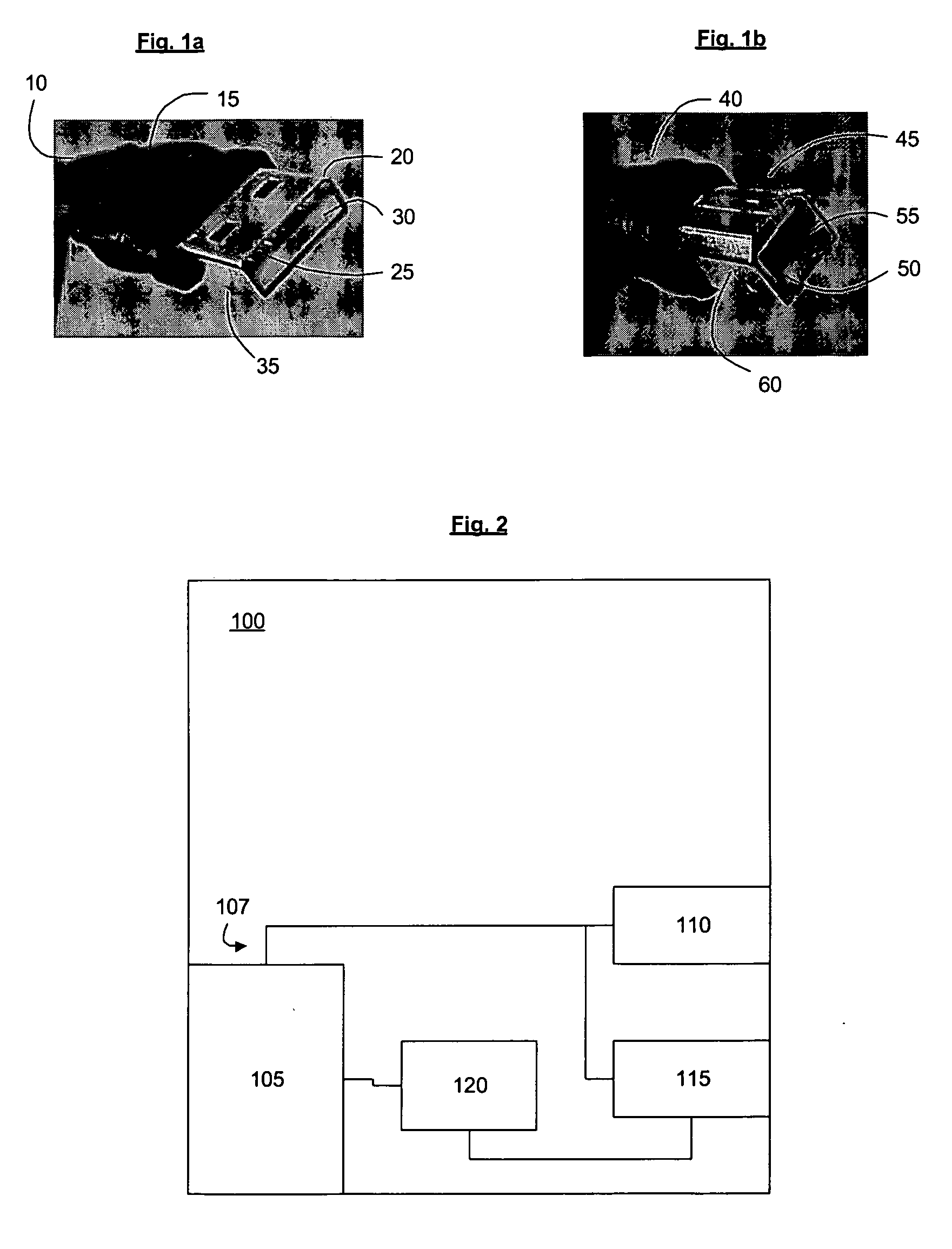
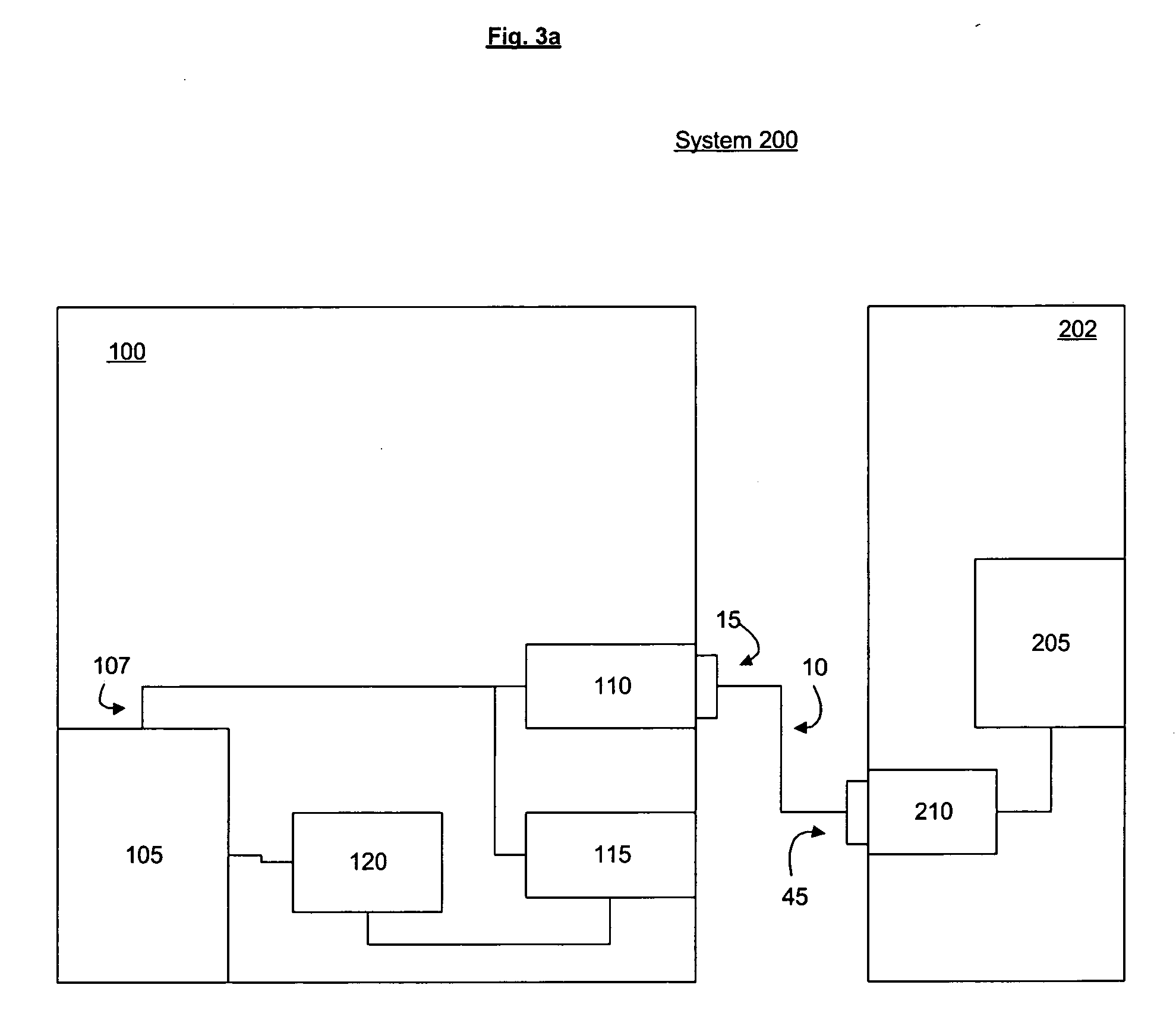
[0012] The present invention may be further understood with reference to the following description and the appended drawings, wherein like elements are referred to with the same reference numerals. As shown in FIG. 1a, a USB cable 10 has a first end 15 with an A connector 20 attached thereto. The cable 10 has typically four wires: two wires for power (+5 volts and ground) and a twisted pair of wires to carry data. The cable 10 may be either a high-speed cable providing data communication at twelve megabits per second or a low-speed cable providing data communication at 1.5 megabits per second. Furthermore, the cable 10 may have a first predefined length (e.g., no greater than 5 meters) when it is the high-speed cable, and a second predefined length (e.g., no greater than 3 meters) when it is the low-speed cable. Those of skill in the art would understand that the cable 10 may be coupled to a further cable via a hub (not shown). When connecting the cable 10 to the further cable, the ...


PUM


Abstract

Described is a system which includes a first device connected to a second device via a USB cable. The cable has a first USB connector and a second USB connector. The first device includes a first USB port, a second USB port and a voltage detector coupled to the second port. The detector detects a voltage at the second port. The first port is configured to accept the first connector and the second port is configured to accept the second connector. The second device includes at least one of a third USB port and a fourth USB port. The third port is configured to accept the first connector and the fourth port is configured to accept the second connector. The first device switches operation between a host state and a client state based on the detected voltage at the second port.

Description

BACKGROUND [0001] A Universal Serial Bus (“USB”) provides a single, standardized, easy-to-use mechanism for connecting computing devices and exchanging data therebetween. A USB connection between, for example, a personal computer (“PC”) and a peripheral device (e.g., PDA, digital camera) is typically accomplished via a USB cable with a four-pin connector on each end. That is, a first end of the cable is an “A” connector and a second end of the cable is a “B” connector. The A connector is plugged into an A port on of a host (e.g., the PC) and the B connector is plugged into a B port of a client (e.g., the peripheral). As well as exchanging data, a low-power peripheral device (e.g., a mouse, a keyboard) may draw power from the PC, while a high-power peripheral device (e.g., a printer) may have its own power supply. [0002] In conventional systems, PCs are typically equipped with A ports and peripheral devices are typically equipped with B ports. Thus, in the USB connection, the PC is u...

Claims


Application Information

Patent Timeline
Patent Type & Authority Applications(United States)
IPC IPC(8): G06F13/38
CPCG06F13/385
Inventor KEPPELER, KARL EDWARD
Owner SYMBOL TECH INC
Learn More