Inkjet recording apparatus and control method of inkjet recording apparatus

a technology of inkjet recording apparatus and recording apparatus, which is applied in the direction of optical elements, printing, instruments, etc., can solve the problems of uneven recording image surface, large apparatus size and weight increase, and uneven image variation, so as to prevent uneven gloss and improve image quality

Active Publication Date: 2006-10-12
KONICA MINOLTA MEDICAL & GRAPHICS INC
View PDF13 Cites 57 Cited by
  • Summary
  • Abstract
  • Description
  • Claims
  • Application Information

AI Technical Summary

Benefits of technology

[0014] The invention has been developed in view of the above-described circumstances, and an object of the invention is to provide an inkjet recording apparatus capable of preventing uneven gloss.

Problems solved by technology

Further, there are sometimes found variation of images, unevenness due to difference in applied ink quantity, partial excessive gloss, etc. in a case that photo-curable ink is used.
These irregularities are obviously found in the recorded area where large quantity of ink is applied.
When water-base ink or oil-base ink is used for recording, most of ink is absorbed into a recording medium, but when photo-curable ink is used, the ink remains on the recording medium and is cured with the ink-deposited portion protruded, which produces an uneven surface of the recorded images due to variation of the deposited ink quantity.
However, the technology described in JP-3248704B needs to mount twice as many recording heads as usual one, thereby making an apparatus larger in size and increased in weight.
The technology described in JP-Tokukai-2003-25613A requires adjustment of jetting amount of ink according to the ink penetrance when using the water-base ink that permeates into a recording medium, and is not applicable to photo-curable ink that is hard to permeate into the recording medium, and that the size and connection state of ink dots are affected by a variation in curing timing by irradiation of light and by the intensity of irradiated light.
The technology described in JP-Tokukai-2003-191601A can obtain a certain level of uniform gloss in recorded images, but cannot obtain a desired level of uniform gloss, that is, cannot determine a jetting amount of invisible ink to realize the desired level of gloss.
In the serial-type inkjet recording apparatus using photo-curable ink, the time from landing of invisible ink to the light irradiation in a bidirectional scanning varies according to the forward and backward movements along the main scanning direction, thus leading to a problem that uneven gloss occurs caused by the uneven dot sizes of invisible ink.

Method used


Image

  • Inkjet recording apparatus and control method of inkjet recording apparatus
  • Inkjet recording apparatus and control method of inkjet recording apparatus
  • Inkjet recording apparatus and control method of inkjet recording apparatus

Examples


first embodiment

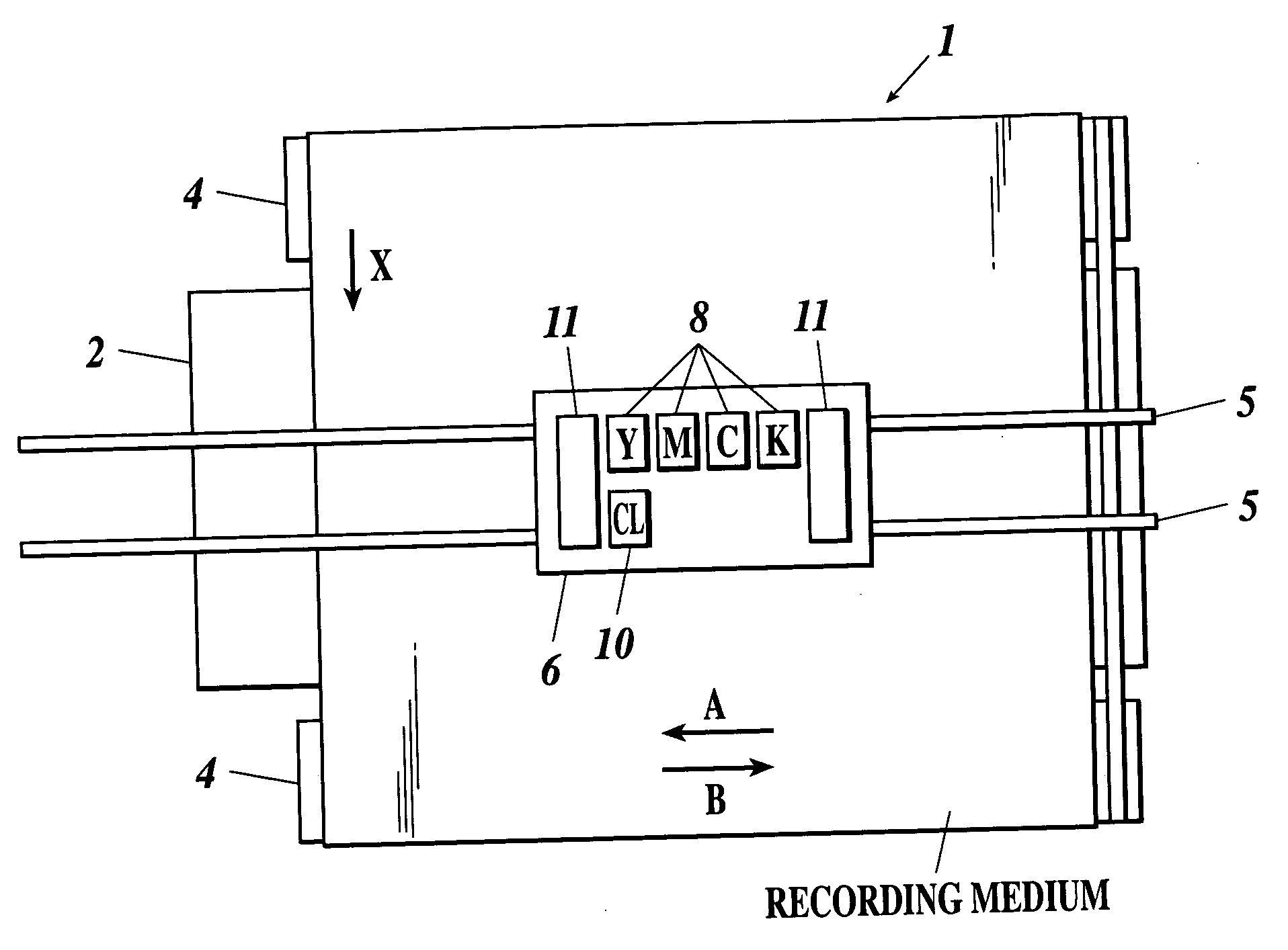
[0074] Referring to FIG. 1, an inkjet recording apparatus 1 according to the embodiment is a serial-type inkjet recording apparatus 1, which comprises a platen 2 formed in a plate shape for supporting a recording medium thereon from its non-recording side.

[0075] Provided under the platen 2 is a conveying section 3 (see FIG. 3) for conveying the recording medium in a conveying direction X perpendicular to main scanning directions A and B. The conveying section 3 includes a plurality of conveying rollers 4, 4, which convey the recording medium from the upstream side to the downstream side in the conveying direction X by the rotation of the conveying rollers 4, 4.

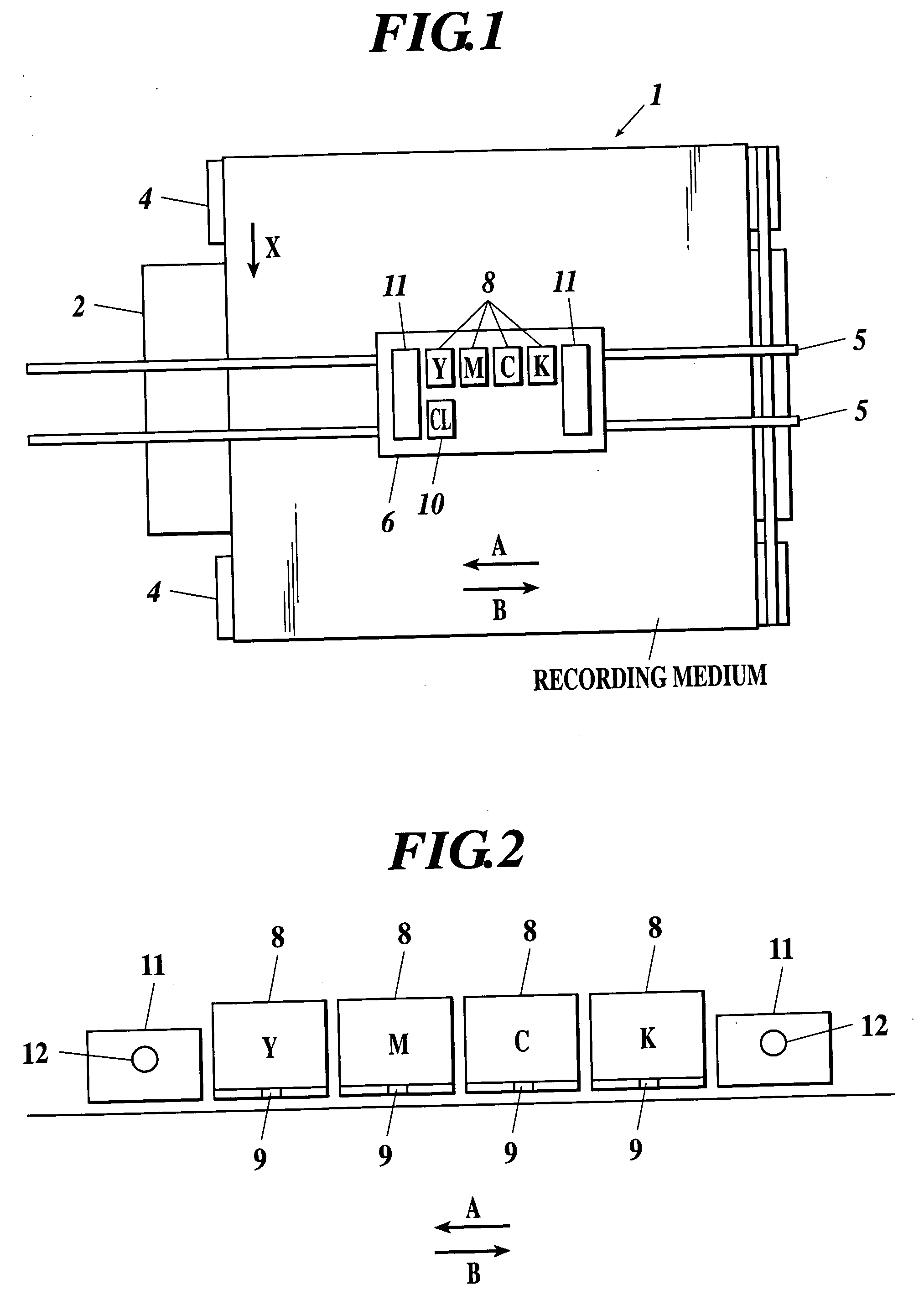
[0076] Provided over the platen 2 are a pair of rod-shaped guide rails 5 and 5 extending in a longitudinal direction of the platen 2. The guide rail 5 supports a carriage 6 as shown in FIG. 2. The carriage 6 is connected with a moving section 7 (see FIG. 3), and able to reciprocate along the guide rails 5 in the main scannin...

second embodiment

[0113] A description will now be given of an inkjet recording apparatus 20 according to a second embodiment of the invention. As shown in FIG. 7, the inkjet recording apparatus 20 of the embodiment differs from the apparatus in the first embodiment in that invisible ink recording heads 10a and 10b are arranged symmetrically on the carriage 6, and ultraviolet irradiating devices 11a and 11b mounted on both sides of the heads have an equal distance from the heads 10a and 10b, respectively.

[0114] With this structure, when the moving direction of the carriage 6 is switched, the invisible ink heads 10a and 10b, and the irradiating devices 11a and 11b, which are used in bidirectional scanning, are both switched. That is, when the carriage 6 moves in the main scanning direction A, the invisible ink is jetted from the head 10b locating at one side with irradiation of ultraviolet rays from the irradiating device 11b locating at the rear side in the moving direction. And when the carriage 6 ...

third embodiment

[0118] A description will be given of an inkjet recording apparatus 30 according to a third embodiment of the invention. As shown in FIG. 9, the inkjet recording apparatus 30 has an invisible ink recording head 10c arranged on the carriage 6, the head 10c having almost double length of the color ink recording head 8. The invisible ink is jetted only in one directional scanning of the invisible ink head 10c as in the first embodiment.

[0119] Accordingly, it is possible to jet the invisible ink on the area, on which the color ink heads 8 jet color inks in bidirectional scanning, from the invisible ink head 10c only in one directional scanning. Further, by properly thinning out the invisible ink, adjacent invisible ink dots can be prevented from randomly connecting with each other to obtain uniform gloss, thereby almost the same effect as in the first embodiment can be achieved.

[0120] The length of the invisible ink head 10c is so formed as to be almost double the length of the color ...


PUM

PropertyMeasurementUnit
widthaaaaaaaaaa
lengthaaaaaaaaaa
unit areaaaaaaaaaaa

Abstract

The inkjet recording apparatus having: a color ink recording head to jet color ink toward a recording medium; an invisible ink recording head to jet invisible ink toward the recording medium; a light irradiating device to irradiate light toward the recording medium to cure ink; a moving section to reciprocate the recording heads and the light irradiating device in a width direction of the recording medium; a conveying section to convey the recording medium; and a control section to perform a control so that while the recording heads and the light irradiating device are moved, the color ink recording head jets the color ink, then the light irradiating device irradiates the color ink with light, and thereafter the invisible ink recording head jets the invisible ink, then the light irradiating device irradiates the invisible ink with light after a lapse of a certain time from the invisible ink jetting.

Description

BACKGROUND OF THE INVENTION [0001] 1. Field of the Invention [0002] The present invention relates to an inkjet recording apparatus and a control method of an inkjet recording apparatus, and more particularly to an inkjet recording apparatus and a control method of an inkjet recording apparatus that record images using invisible ink. [0003] 2. Description of the Related Art [0004] There have been widely known an inkjet type recording apparatus (hereinafter referred to as “inkjet recording apparatus”) as a recording apparatus that can correspond to the demand of small quantity and various kinds of recording suited to the occasion. Inkjet recording apparatuses generally jet droplets of ink from nozzles formed on a recording head at the surface facing a recording medium, land and fix the ink on the recording medium to record images on the medium. The inkjet recording apparatus differs from image recording method used in a conventional gravure printing method or flexography printing meth...

Claims


Application Information

Patent Timeline
Patent Type & Authority Applications(United States)
IPC IPC(8): B41J2/01
CPCB41J11/002B41J2/2114B41J11/0021B41J11/00214
Inventor HOSHINO, YOSHIHIDE
Owner KONICA MINOLTA MEDICAL & GRAPHICS INC
Why Eureka
Try Eureka