Workpiece inspection system

Inactive Publication Date: 2006-10-26
MECTRON ENG
View PDF17 Cites 90 Cited by
  • Summary
  • Abstract
  • Description
  • Claims
  • Application Information

AI Technical Summary

Benefits of technology

[0007] In satisfying the above need, as well as overcoming the enumerated drawbacks and other limitat

Problems solved by technology

It is not uncommon for one or more of the processes to produce a crack in the part or other defect.
The occurrence of such defects is often not adequately monitored through random part selection or other quality assurance processes which do not provide 100% inspection.
Although known inspection systems are generally useful, they have certain limitations.
Many of the presently available non-contact gauging systems require complex data processing

Method used


Image

  • Workpiece inspection system
  • Workpiece inspection system
  • Workpiece inspection system

Examples


Embodiment Construction

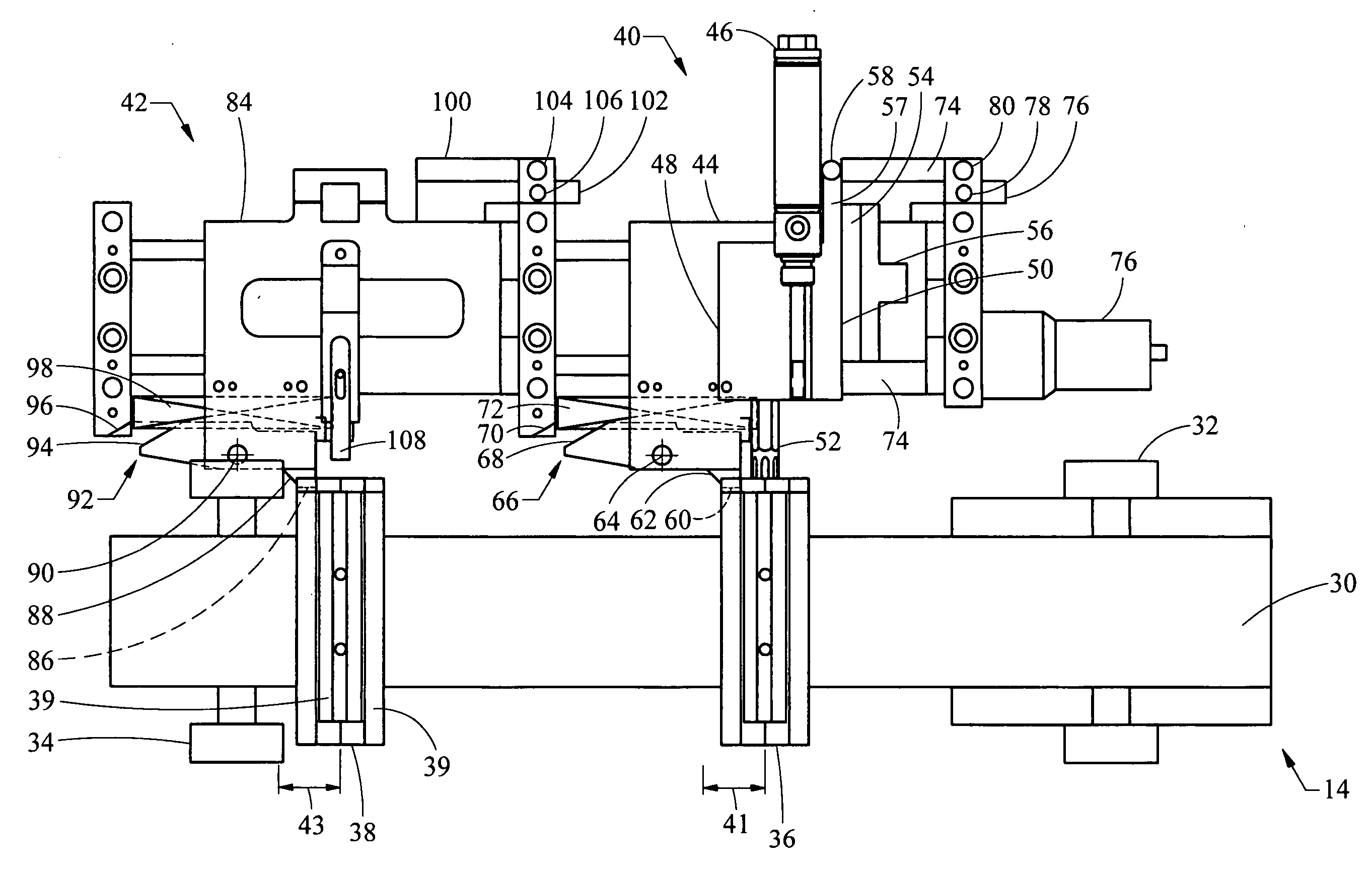
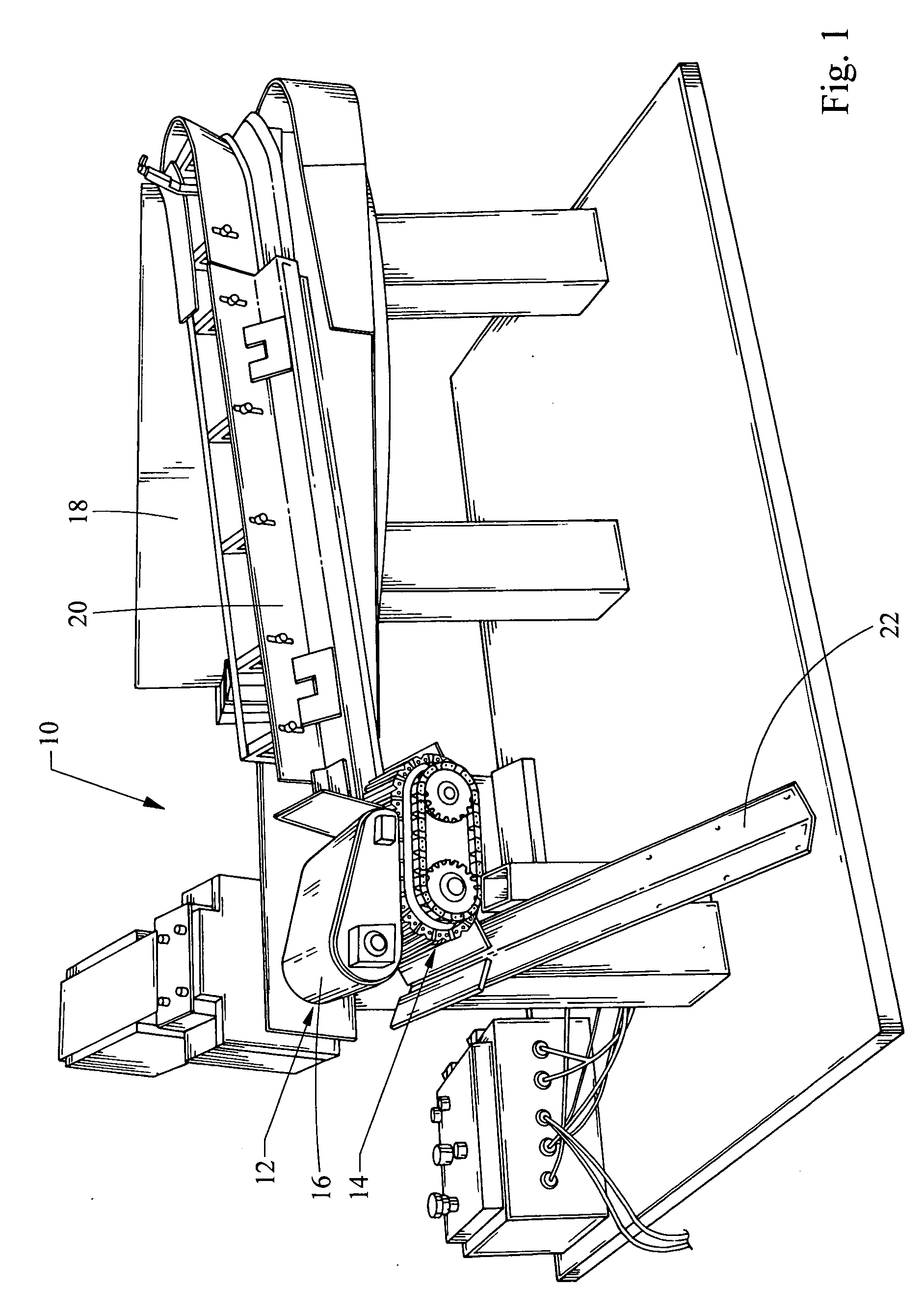
[0016] Referring now to FIG. 1, a system embodying the principles of the present invention is illustrated therein and designated at 10. As its primary components, the system 10 includes an inspection station 12 that uses a linear conveyor 14 to translate parts while a belt drive 16 rotates the parts relative to the conveyor 14.

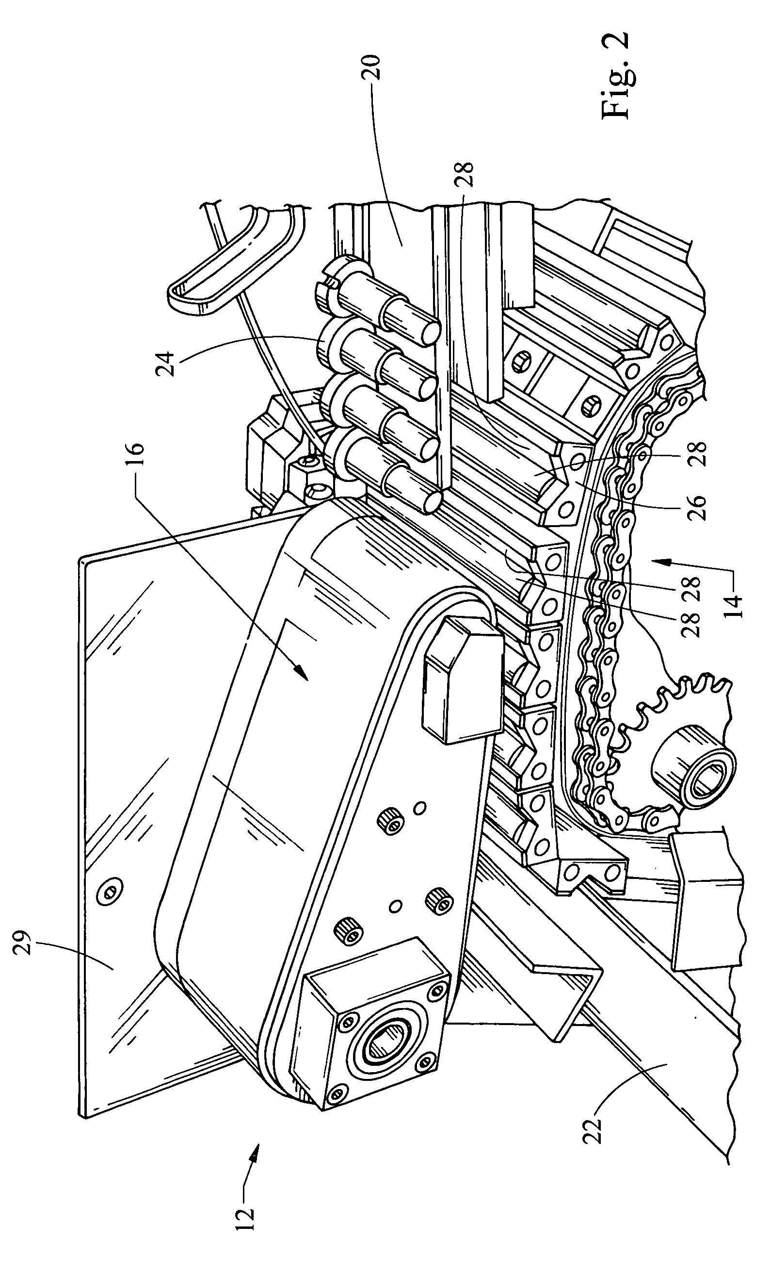
[0017] The parts are provided from a hopper 18 along a track 20. The parts translate along the track 20 due to gravity, vibration, or other means reaching the inspection station 12. Parts 24 are located in the inspection station 12 by an array of fixtures 26 forming part of the conveyor 14, as shown in FIG. 2. The belt drive 16 moves at a speed different than the speed of the conveyor 14. For example, the belt drive 16 may move in the same direction as the conveyor 14 but at a slightly faster speed. Alternatively, the belt drive 16 may move slower than the conveyor 14 or even in the opposite direction. Another embodiment may include a stationary pad that fric...


PUM


Abstract

An inspection station for a workpiece including a conveyor, a mechanism for rotating the workpiece, and a probe. The conveyor includes a fixture for locating the workpiece and the conveyor is configured to translate the workpiece in a linear manner. A mechanism, such as a belt, engages the workpiece thereby rotating the workpiece within the fixture. The probe is configured to indicate if the workpiece conforms to quality criteria. To facilitate inspection while the conveyor translates the workpiece, the probe is attached to a stage where the stage is configured to move the probe synchronously with the workpiece over an inspection region.

Description

FIELD OF THE INVENTION [0001] This invention relates to a device for inspecting components and particularly to one using a probe that translates synchronously with the component over an inspection region. BACKGROUND OF THE INVENTION [0002] Presently, there is an ever increasing demand to obtain high quality products which has resulted in a significant increase in the use of inspection systems. In order for a complex machine to operate as designed, it is necessary that all of its sub-components comply with quality criteria. In some manufacturing settings, customers require 100% inspection of component parts. For example, fasteners used in the automobile industry and elsewhere often must be individually inspected to determine if they meet product specifications. [0003] When producing fasteners, the process often begins with wire stock which is fed into a cold heading or screw type forming machine. The part is die-formed or cut in a machine into a shape that may include several diamete...

Claims


Application Information

Patent Timeline
IPC IPC(8): G01M19/00G01M99/00
CPCG01B5/18G01N27/9026G01N27/902
Inventor HANNA, JAMES L.
Owner MECTRON ENG
Why Eureka
Try Eureka