Unlock instant, AI-driven research and patent intelligence for your innovation.

Common aperture vision system

Active Publication Date: 2006-11-02
BAE SYST INFORMATION & ELECTRONICS SYST INTERGRATION INC
View PDF35 Cites 6 Cited by
  • Summary
  • Abstract
  • Description
  • Claims
  • Application Information

AI Technical Summary

Benefits of technology

[0003] There is a need for an optical multi-waveband common aperture system that eliminates or reduces comatic and astigmatic aberrations.
[0007] The unique common aperture configuration described herein provides an extremely compact device with well corrected imagery in at least two distinct spectral wavebands that can be combined using image fusion.

Problems solved by technology

Beamsplitters, however, introduce a number of optical distortions.

Method used


Image

  • Common aperture vision system
  • Common aperture vision system
  • Common aperture vision system

Examples


Embodiment Construction

[0024] Where a beam impinging onto a dichroic beamsplitter has optical power, the beam transmitted through the beamsplitter is distorted. Two principal types of aberrations are introduced into the transmitted beam: astigmatism and axial coma. Astigmatic aberration is a phenomenon in which lines or bars at different orientations are not all simultaneously in focus. As a result, the same point of light becomes imaged as a bar elongated in one of two orthogonal directions depending on the level of focus. Coma is an aberration which causes rays from an off-axis point of light in the object plane to create a trailing “comet-like” blur directed away from the optical axis. A lens with considerable coma may produce a sharp image in the center of the field, but become increasingly blurred toward the edges.

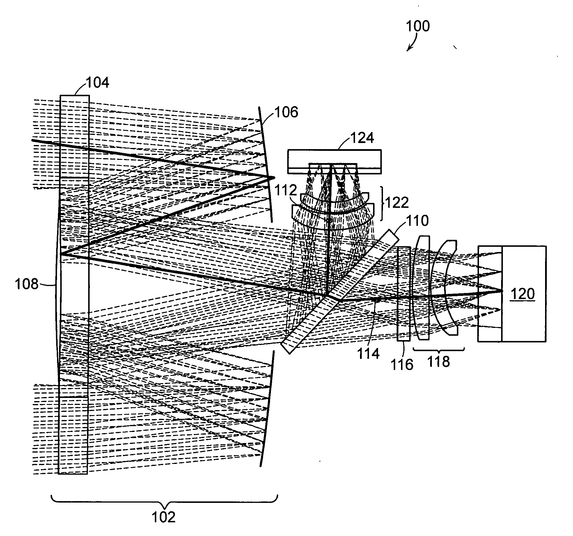
[0025] The embodiments described below with reference to FIGS. 1-3 comprises two spectral channels. By inserting additional beamsplitters into the optical train, additional spectral channe...


PUM


Abstract

An optical device comprises a dichroic beamsplitter for splitting an object beam into a reflected beam having a first waveband and a transmitted beam having a second waveband; an astigmatism-correcting lens element, disposed in the optical path of the transmitted beam; and a coma-correcting lens element, disposed in the optical path of the transmitted beam.

Description

RELATED APPLICATION [0001] This application claims the benefit of U.S. Provisional Application No. 60 / 585,726 filed on Jul. 7, 2004. The entire teachings of the above application are incorporated herein by reference.BACKGROUND OF THE INVENTION [0002] Optical sensors and detectors, including night vision systems, often use multiple imaging channels, each operating at a specified waveband. Imaging channels often share a common aperture of an objective piece. In many cases, dichroic beamsplitters are employed to separate the imaging channels. Beamsplitters, however, introduce a number of optical distortions. SUMMARY OF THE INVENTION [0003] There is a need for an optical multi-waveband common aperture system that eliminates or reduces comatic and astigmatic aberrations. [0004] The present invention is directed to a multi-waveband optical system suitable for use as a vision device that employs at least two imaging channels acquired through a common aperture, each channel separated using ...

Claims


Application Information

Patent Timeline
IPC IPC(8): G02B27/14
CPCG02B13/22G02B17/0808G02B27/0025G02B17/0852G02B17/0896G02B17/0816
Inventor COUTURE, MICHAEL E.PLOTSKER, VADIM
Owner BAE SYST INFORMATION & ELECTRONICS SYST INTERGRATION INC
Features
  • R&D
  • Intellectual Property
  • Life Sciences
  • Materials
  • Tech Scout
  • Unparalleled Data Quality
  • Higher Quality Content
  • 60% Fewer Hallucinations
Learn More