
Spiral shaped filter

a filter and spiral shape technology, applied in the field of spiral shape filters, can solve the problems of high operative mortality associated with all of these surgical treatments, potentially fatal condition known as pulmonary embolism,

Inactive Publication Date: 2006-11-09
CRUX BIOMEDICAL
View PDF35 Cites 44 Cited by
  • Summary
  • Abstract
  • Description
  • Claims
  • Application Information

AI Technical Summary

Benefits of technology

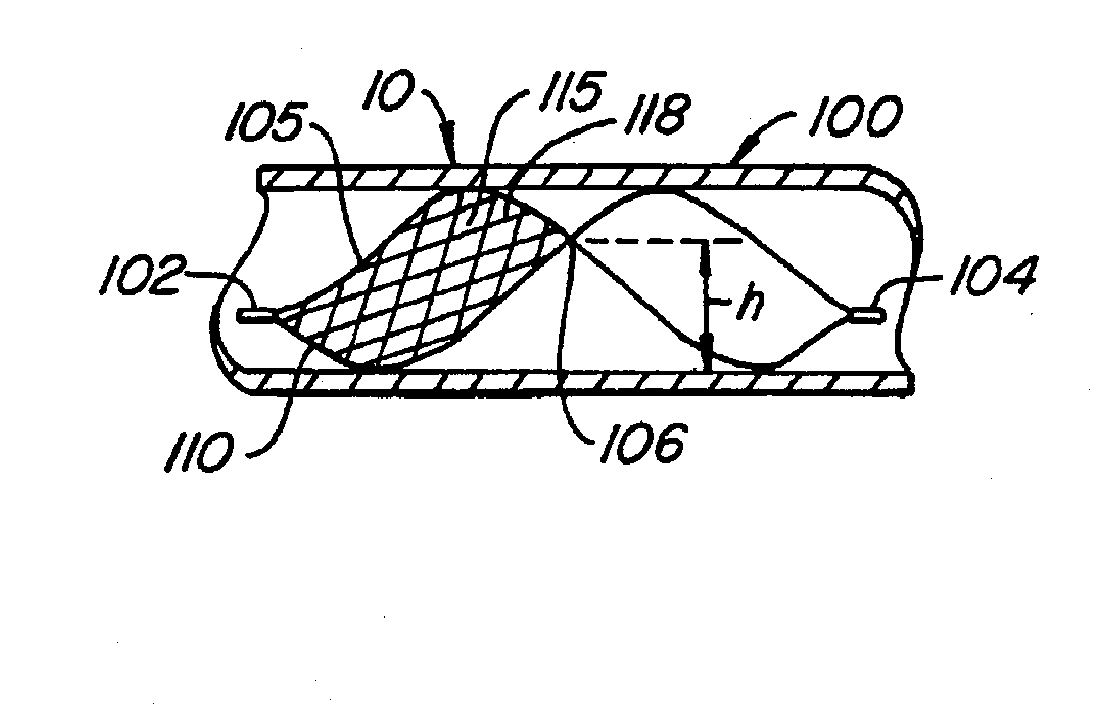
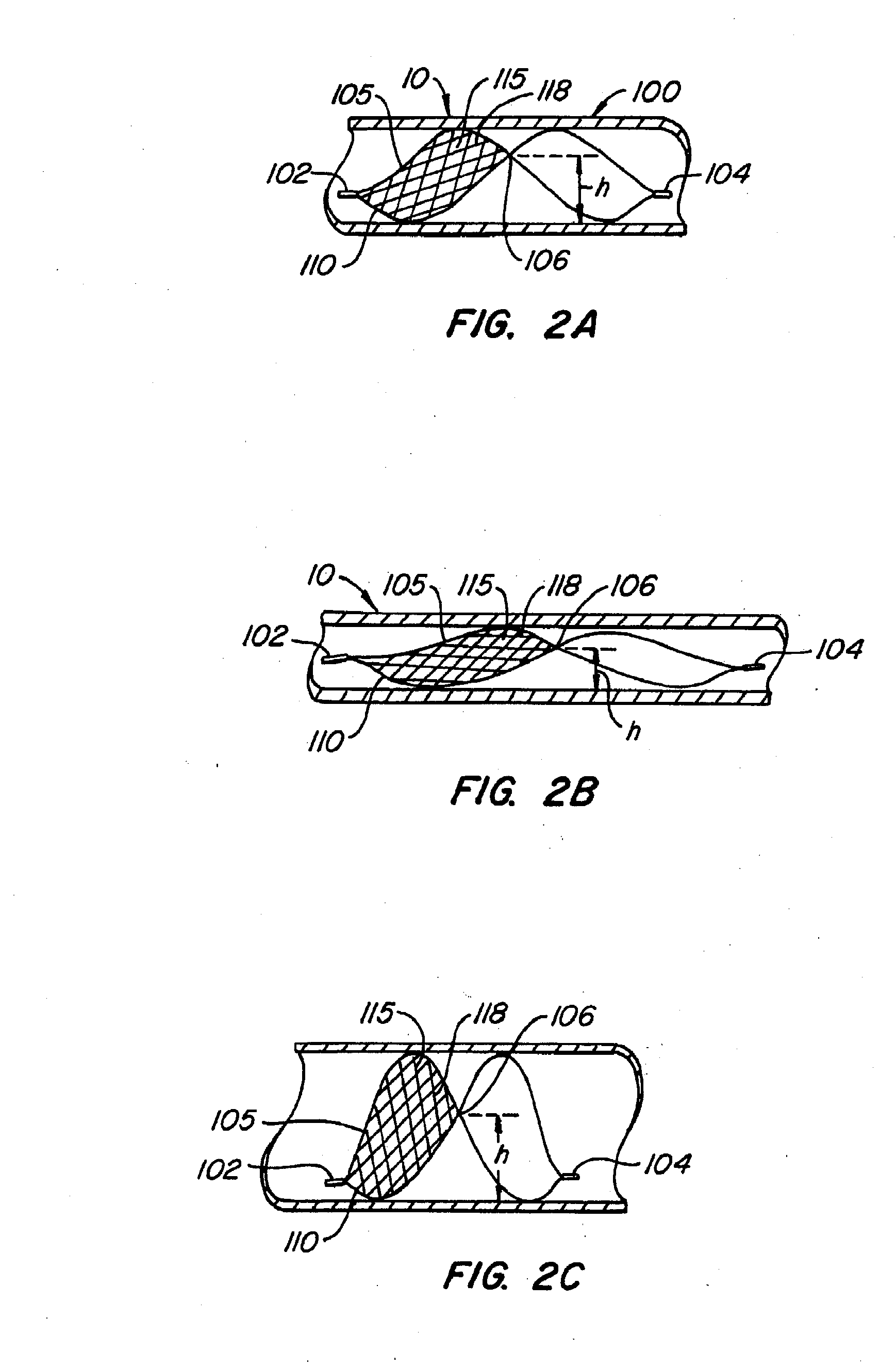
"The present invention provides filters with a unique structure that allows for easy attachment of a filtering structure and the release of pharmacological agents. The filter includes a first spiral support member and a second spiral support member that creates an open loop between the first and second ends of the first spiral support member. The filtering structure is attached to the open loop using a release line. The second spiral support member can be joined to the first spiral support member at the first end or the second end. The filter also includes a third support member that is positioned between the first and second spiral support members and has a sinusoidal shape. The third support member can be attached to the first and second spiral support members at the first end or the second end. The filter can also have a multi-lumen structure that is attached to the loop and can release pharmacological agents. The technical effects of this invention include easy attachment of a filtering structure and the release of pharmacological agents."

Problems solved by technology

This condition is known as deep vein thrombosis (DVT), which can cause a potentially fatal condition known as pulmonary embolism (PE).
While effective at preventing PE, these methods were associated with significant mortality and morbidity (see, e.g., Kinney TB, Update on inferior vena cava filters, JVIR 2003; 14:425-440, incorporated herein by reference).
Operative mortality associated with all of these surgical treatments remained high and therefore limited their applicability.
These reported problems include tilting which makes it difficult to recapture the device and compromises filtration capacity.
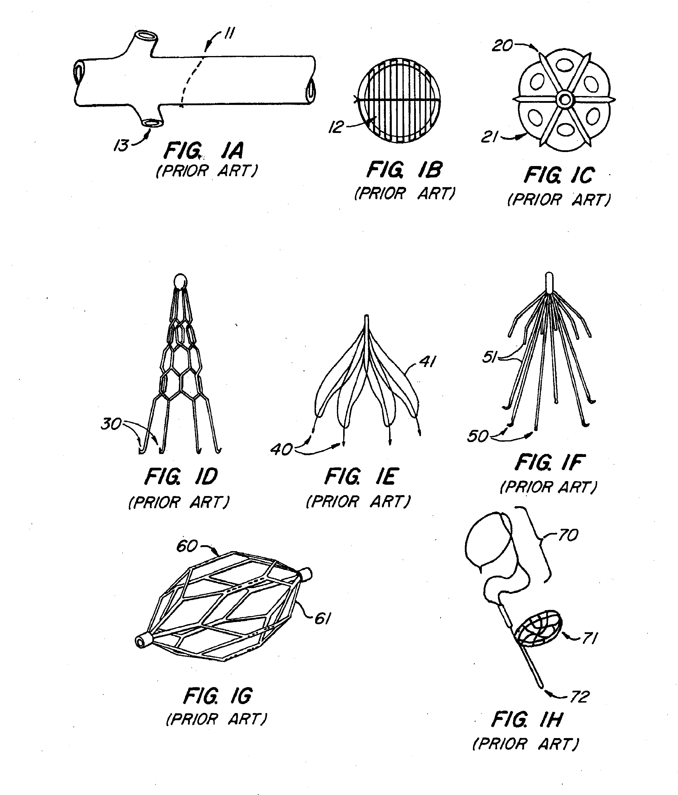
Hooks 30, 40, 50, 60 used to secure these devices have been reported to perforate the vessel wall, cause delivery complications, and fracture.
All of these described devices share the common limitation that they can be retrieved from only one end.

Method used


Image

  • Spiral shaped filter
  • Spiral shaped filter
  • Spiral shaped filter

Examples


Embodiment Construction

[0038] There remains a clinical need for improved endoluminal filter devices and methods. Improved endoluminal filter devices provide effective filtration over a range of lumen sizes and are easy to deploy into and retrieve from a lumen. In addition, improved endoluminal filter devices minimize thrombosis formation or tissue ingrowth on the device and are resistant to migration along the lumen. Improved endoluminal filter devices also minimize device fatigue by eliminating barbs, hooks or other sharp curve design features that can produce stress points that lead to fatigue. Embodiments of the filter devices of the present invention provide many and in some cases all of the features of improved endoluminal filters and have a number of uses such but are not limited to: embolic protection, thrombectomy, vessel occlusion, and tethered or untethered distal protection.

[0039] Several embodiments of the present invention provide improved filtration devices that are durable, provide effecti...


PUM

PropertyMeasurementUnit
diameteraaaaaaaaaa
diameteraaaaaaaaaa
angleaaaaaaaaaa

Abstract

In one embodiment of the present invention there is provided a filter having a first spiral support member having a first end and a second end, a second spiral support member positioned adjacent the first spiral support member to form an open loop between the first end and the second end of the first spiral support member; and a filtering structure attached to the open loop. In another embodiment of the present invention there is provided a filter having a first spiral support member having a first end and a-second end; a second spiral support member positioned adjacent the first spiral support member to form a loop between the first end and the second end; a material covering a portion of the first and the second spiral support members; and a structure attached to the loop.

Description

CROSS-REFERENCE TO RELATED APPLICATIONS [0001] This application claims the benefit of U.S. Provisional Application No. 60 / 641,327, filed Jan. 3, 2005, U.S. Provisional Application No. 60 / 668,548, filed Apr. 4, 2005; U.S. Provisional Application No. 60 / 673,980, filed Apr. 21, 2005 each of which is incorporated herein by reference and, this application is related to the following copending patent applications filed herewith: application Ser. No. (Not Yet Assigned) [Attorney Docket No. 31688-701.203] entitled “Retrievable Endoluminal Filter”; application Ser. No. (Not Yet Assigned) [Attorney Docket No. 31688-701.202] entitled “Coated Endoluminal Filter”; application Ser. No. (Not Yet Assigned) [Attorney Docket No. 31688-701.201] entitled “Endoluminal Filter”; application Ser. No. (Not Yet Assigned) [Attorney Docket No. 31688-701.205] entitled “Endoluminal Filter”; application Ser. No. (Not Yet Assigned) [Attorney Docket No. 31688-701.204] entitled “Spiral Shaped Filter”; application Se...

Claims


Application Information

Patent Timeline
Patent Type & Authority Applications(United States)
IPC IPC(8): D01H7/86
CPCA61F2/01A61F2002/011A61F2002/016A61F2250/0067A61M25/0021A61M25/007A61B17/221A61M2025/004A61F2002/018A61F2230/0008A61F2230/001A61F2230/0067A61F2230/0095A61M2025/0037A61F2/011
Inventor JOHNSON, ERICFOGARTY, THOMASARKO, FRANKELKINS, JEFFSEERY, MARTIN
Owner CRUX BIOMEDICAL
Learn More