
Head mounted display devices

a display device and head mount technology, applied in the field of displays, can solve the problems of large product size, heavy weight, and high cost of many applications, and achieve the effects of improving the quality of display and reducing the cost of production

Active Publication Date: 2006-11-09
SYNOPSYS INC
View PDF77 Cites 150 Cited by
  • Summary
  • Abstract
  • Description
  • Claims
  • Application Information

AI Technical Summary

Benefits of technology

[0008] Various embodiments are described herein. One embodiment comprises a head mounted display for displaying images comprising an image formation device comprising a plurality of pixels selectively adjustable for producing spatial patterns; imaging optics disposed with respect to the image formation device to r...

Problems solved by technology

As many components are included in the optical systems, the products become larger, heavier, and more expensive than desired for many applications.

Method used


Image

  • Head mounted display devices
  • Head mounted display devices
  • Head mounted display devices

Examples


Embodiment Construction

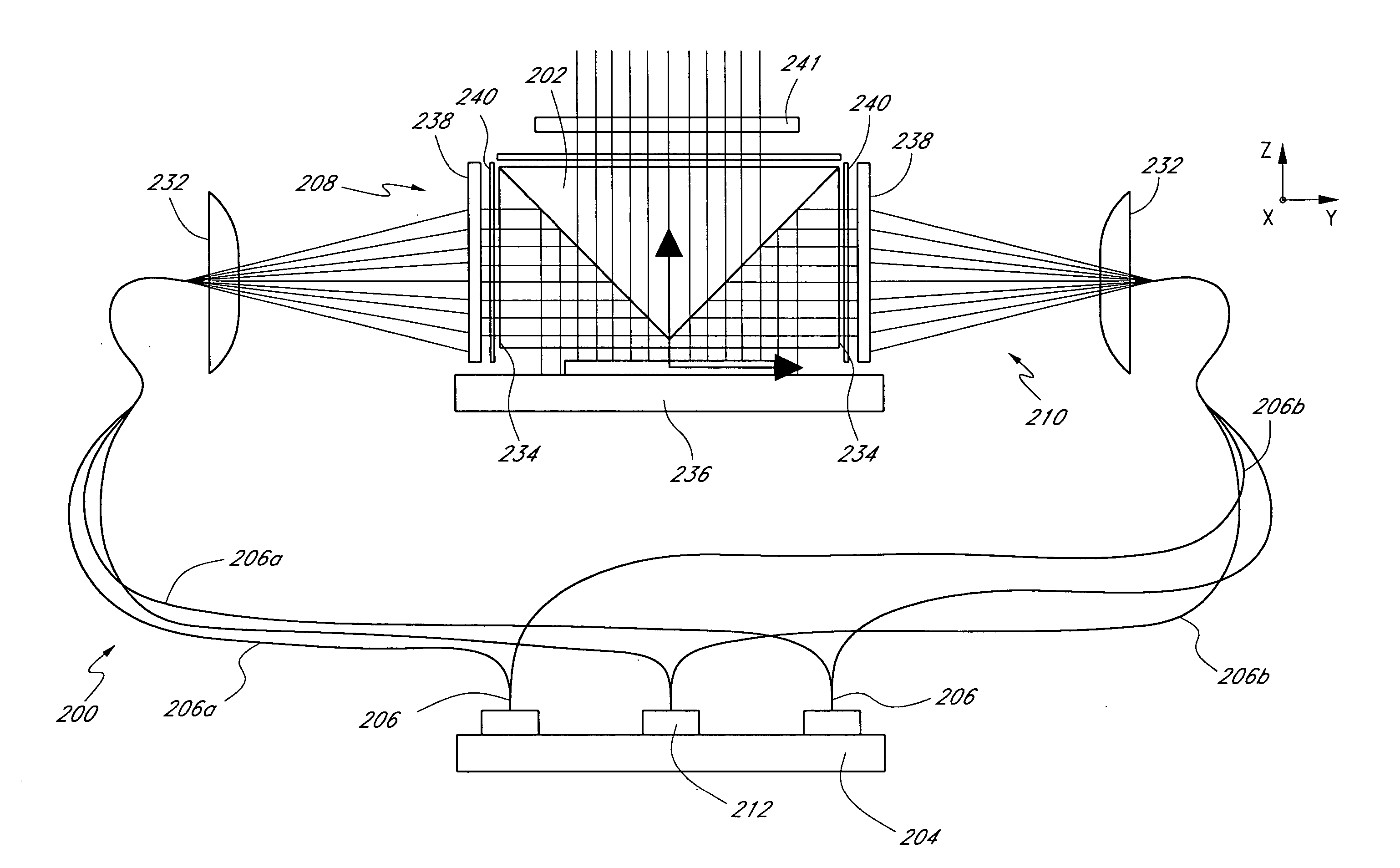
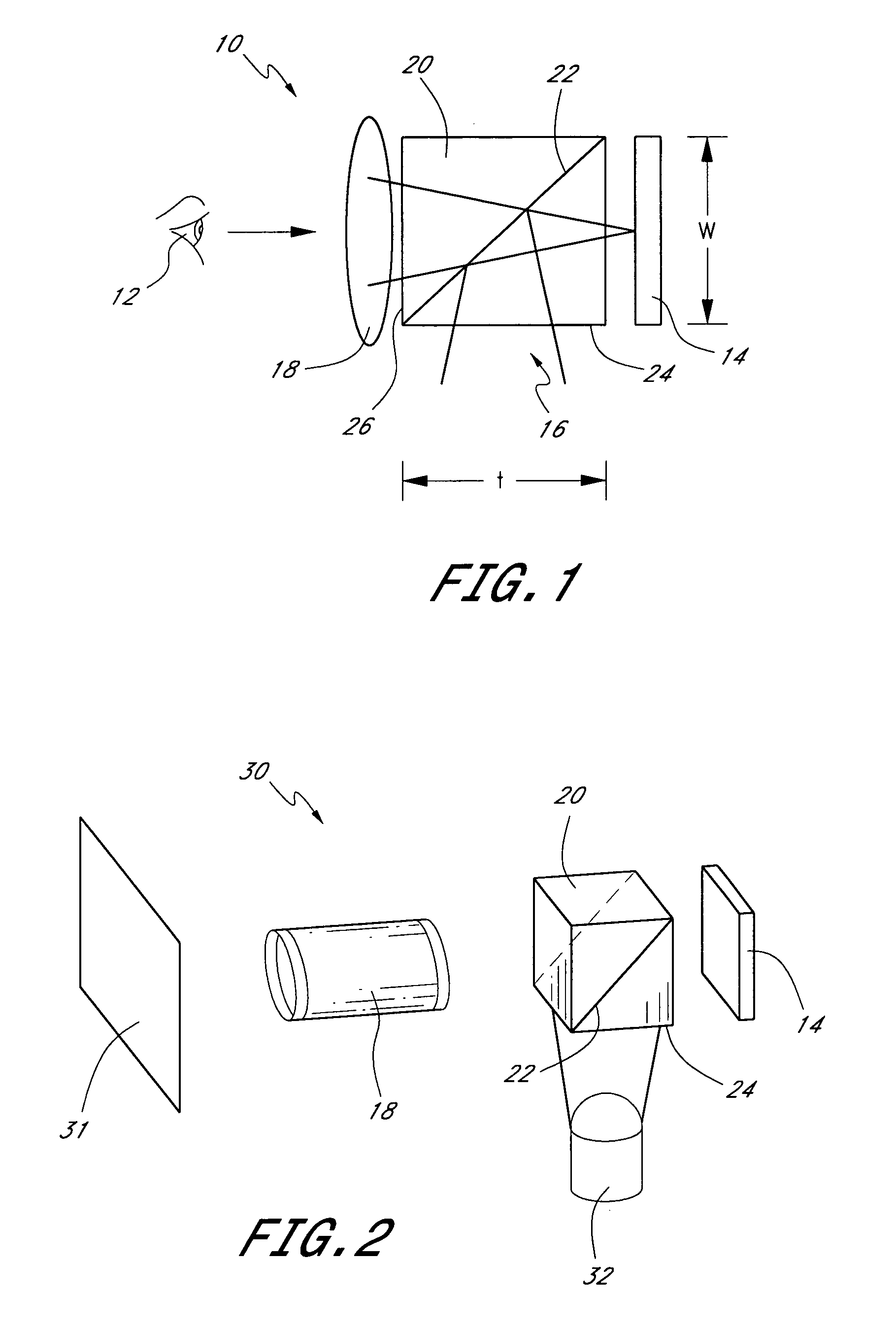
[0069] To present graphics or other visual information to a viewer, images and / or symbols, e.g., text or numbers, can be projected onto a screen or directed into the viewer's eye. FIG. 1 schematically illustrates a display 10 disposed in front of a viewer 12 (represented by an eye). In a preferred embodiment, this display 10 includes a spatial light modulator 14 that is illuminated with light 16 and imaged with imaging or projection optics 18. The spatial light modulator 14 may comprise, for example, a reflective polarization modulator such as a reflective liquid crystal display. This liquid crystal spatial light modulator preferably comprises an array of liquid crystal cells each which can be individually activated by signals, e.g., analog or digital, to produce a high resolution pattern including characters and / or images. More generally, the spatial light modulator may comprise an array of modulators or pixels that can be selectively adjusted to modulate light. The projection opti...


PUM


Abstract

One embodiment of the invention comprises a simplified light-weight head mounted displays comprising an off-axis combiner and a pair of plastic lenses. One of the lenses is a rotationally symmetric optical element and one of the lens is a non-rotationally symmetric optical element. This non-rotationally symmetric optical element comprises first and second lens surfaces that are tilted and decentered with respect to each other. One of these first and second lens surfaces may also include diffractive feature to provide a diffractive or holographic optical element for color correction.

Description

RELATED APPLICATIONS [0001] This application claims priority to U.S. Provisional Application No. 60 / 677,666, filed May 3, 2005 and entitled “Simple Helmet Mounted Display With Plastic Element” (Attorney Docket No. OPTRES.053PR), which is incorporated herein by reference in its entirety. This application also incorporates by reference U.S. patent application Ser. No. 10 / 852,728, filed on May 24, 2004 and entitled “Beamsplitting structures and methods in optical systems” (Attorney Docket No. OPTRES.022A1), U.S. patent application Ser. No. 10 / 852,679, filed on May 24, 2004 and entitled “Apparatus and methods for illuminating optical systems” (Attorney Docket No. OPTRES.022A2), U.S. patent application Ser. No. 10 / 852,669, filed on May 24, 2004 and entitled “Light distribution apparatus and methods for illuminating optical systems” (Attorney Docket No. OPTRES.022A3), and U.S. patent application Ser. No. 10 / 852,727, filed on May 24, 2004 and entitled “Optical combiner designs and head mou...

Claims


Application Information

Patent Timeline
IPC IPC(8): G02B27/14
CPCG02B27/0037G02B27/0172G02B27/1033G02B27/1066G02B2027/0123G02B27/145G02B27/149G02B2027/011G02B27/144
Inventor MCGUIRE, JAMES P.
Owner SYNOPSYS INC
Learn More