Instant wire splice wrap

a wire splicing and wire technology, applied in the direction of cable termination, electric cable installation, cable fittings, etc., can solve the problems of prophylactic-type wrap, non-conductive, hollow core to break away, etc., and achieve the effect of quick and secure splicing of electrical wires

Inactive Publication Date: 2006-11-16
GREGOREK MARK R
View PDF18 Cites 23 Cited by
  • Summary
  • Abstract
  • Description
  • Claims
  • Application Information

AI Technical Summary

Benefits of technology

[0016] The present invention is directed toward a method for splicing electrical wires. The wires to be spliced are first stripped of a portion of insulation exposing the bare ends of the wires. A hollow core with a wrap consisting of a non-conductive, flexible, latex-based or other type of rubber or plastic material rolled back upon itself about the core is then slid over the terminal end of a first wire to be spliced. Next, the bare end of a second wire to be spliced is brought in contact with the bare end of the first wire, and the two wires are pressed or twisted together by hand. The hollow core is then positioned over the area where the insulation ends of the first wire to be spliced and pressed firmly by hand. This pressure may cause the hollow core to break away, or fracture, thereby locking the non-conductive, prophylactic-type wrap in place. The wire wrap is then unrolled down the wire and tightly embraces, encompasses, and secures itself around the bare conductors of the wires to be spliced. The wrap completely encompasses the bare conductors, thereby insulating and protecting the splice.
[0017] The present invention is also directed toward a device for quickly and securely splicing electrical wires by those with less than normal dexterity. The present invention comprises a wire wrap, rolled back upon itself around a hollow core, which is adapted to fit over an electrical wire. The present invention is installed in seconds by sliding the core over a terminal end of one or more wires to be spliced with one or more other wires. The device is then positioned over the end of one wire to be spliced and pressed firmly by hand. The pressure causes the hollow core to break, thereby locking the present invention in place over the terminal end of a first wire to be spliced. The wire wrap is then unrolled over to the bare conductors of the wires to be spliced until the wrap is fully unrolled. The device protects the spliced wires from short circuits and contaminants while securely holding the splice in place.

Problems solved by technology

This pressure may cause the hollow core to break away, or fracture, thereby locking the non-conductive, prophylactic-type wrap in place.

Method used


Image

  • Instant wire splice wrap
  • Instant wire splice wrap
  • Instant wire splice wrap

Examples


Embodiment Construction

[0034] A detailed illustrative embodiment of the present invention is disclosed herein. However, techniques, systems, and operating structures in accordance with the present invention may be embodied in a wide variety of forms and modes, some of which may be quite different from those in the disclosed embodiment. Consequently, the specific structural and functional details disclosed herein are merely representative, yet in that regard, they are deemed to afford the best embodiment for the purposes of disclosure and to provide a basis for the claims herein, which define the scope of the present invention. The following presents a detailed description of a preferred embodiment (as well as some alternative embodiments) of the present invention.

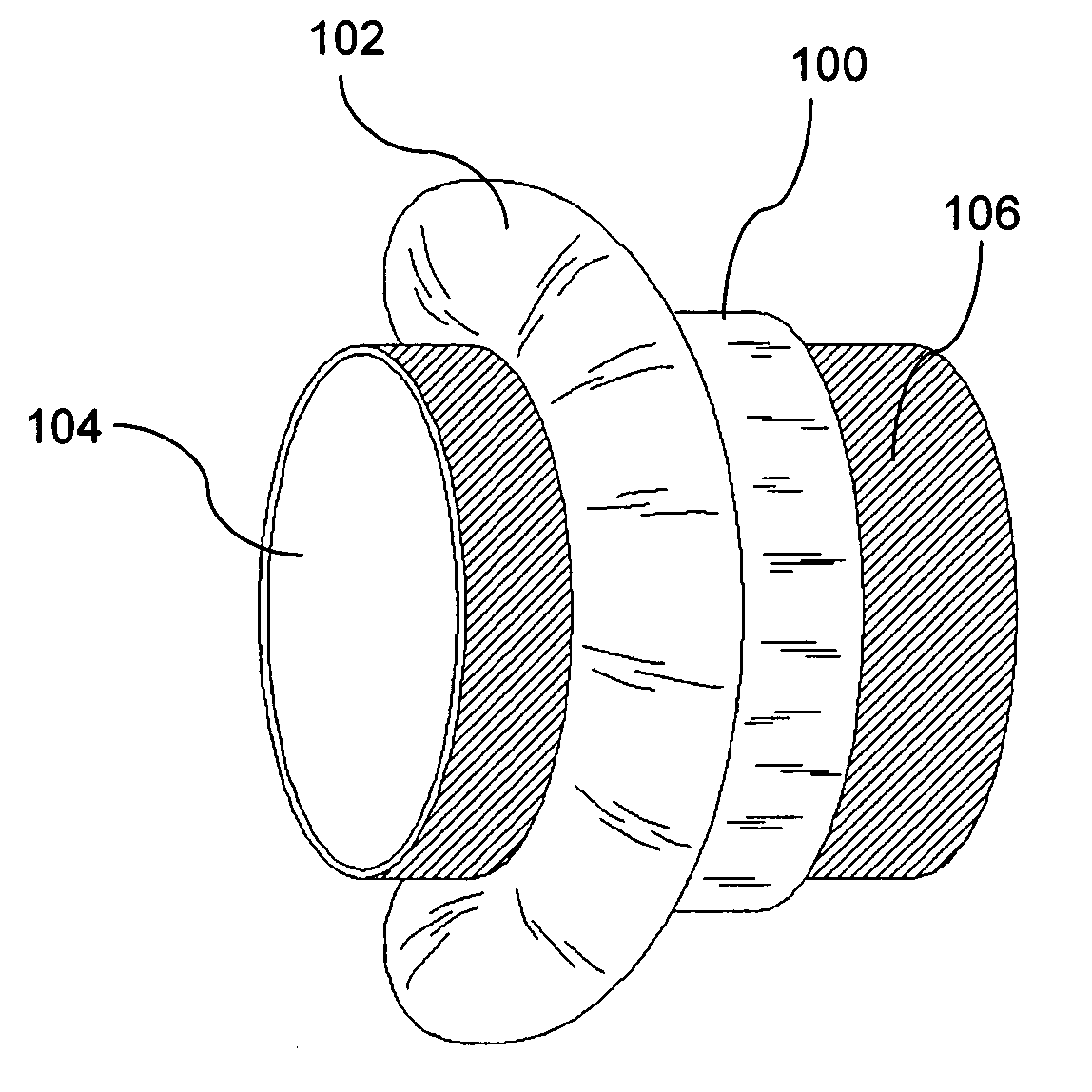
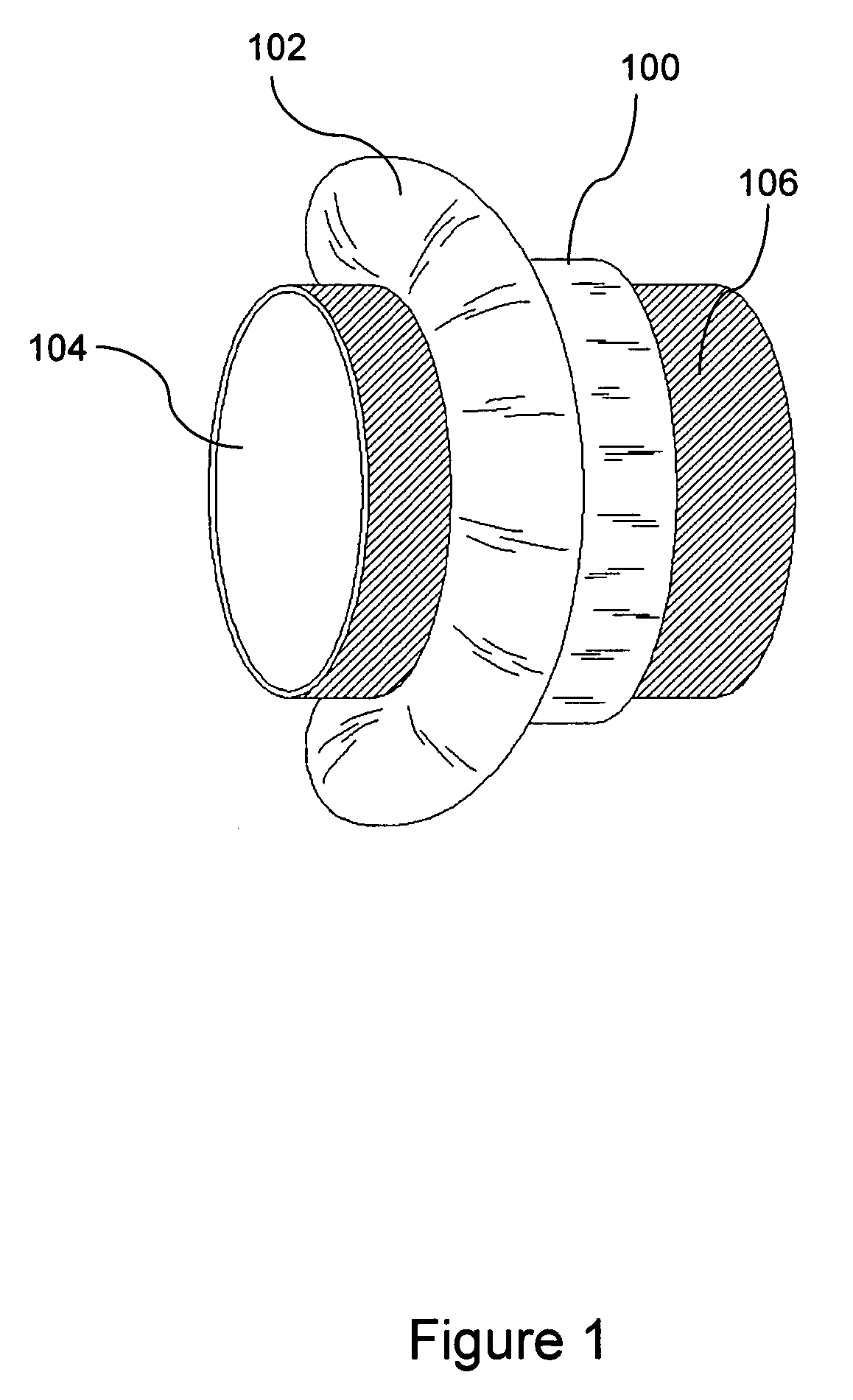
[0035] Referring to FIG. 1, the preferred embodiment of the present invention is depicted in its packaged form. Wrap 100 is preferably open at both ends and may comprise plastic, any substances commonly associated with plastic, derivatives there...


PUM


Abstract

A method and apparatus for quickly, economically, and securely splicing wires is disclosed. The quick wire splice wrap is installed in seconds without the use of external crimping tools, implements, or appliances.

Description

FIELD OF THE INVENTION [0001] The present invention relates generally to the field of wire splices and connectors and, more particularly, to a method and apparatus for splicing wires quickly, economically, and effectively without the use of external crimping instruments. BACKGROUND OF THE INVENTION [0002] Electrical wire splices and connectors are commonly used in the manufacturing, re-manufacturing, reverse manufacturing, modifying, updating, and replacement of electrical wire assemblies. For example, in the automotive industry, there may be numerous wire splices and / or connectors in one wire assembly in order to transmit electrical energy to outlying lights and various automotive accessories. In addition, electrical wire splices are commonly used to repair, replace, or add common electrical household devices, such as lights, electrical switches, outlets, and ceiling fans. [0003] There are several common methods of splicing electrical wires or connectors. One method of splicing ele...

Claims


Application Information

Patent Timeline
Patent Type & Authority Applications(United States)
IPC IPC(8): H02G15/02
CPCH01R4/70H01R4/22
Inventor GREGOREK, MARK R.
Owner GREGOREK MARK R
Why Eureka
Try Eureka