Ice cutter

a cutting device and ice technology, applied in water cleaning, hydraulic engineering, construction, etc., can solve the problems of arduousness and achieve the effect of quick shave through the i

Inactive Publication Date: 2006-11-16
PAVATI ENG
View PDF13 Cites 21 Cited by
  • Summary
  • Abstract
  • Description
  • Claims
  • Application Information

AI Technical Summary

Benefits of technology

[0011] Another advantage of the present invention is that one size auger is utilized for several diameters of holes by the interchanging of the cutting plate on the end of the auger.
[0012] Yet another advantage of the present invention is that a single connector holds the shaped plate and centering bit to the shaft.
[0013] Still yet another advantage of the present invention is that it is very efficient and can be driven by a battery operated drive apparatus.

Problems solved by technology

Fishing in winter time can be rather arduous and requires making a hole through the ice in order to use the baited hook to attract fish thereto.

Method used


Image

  • Ice cutter
  • Ice cutter
  • Ice cutter

Examples


Embodiment Construction

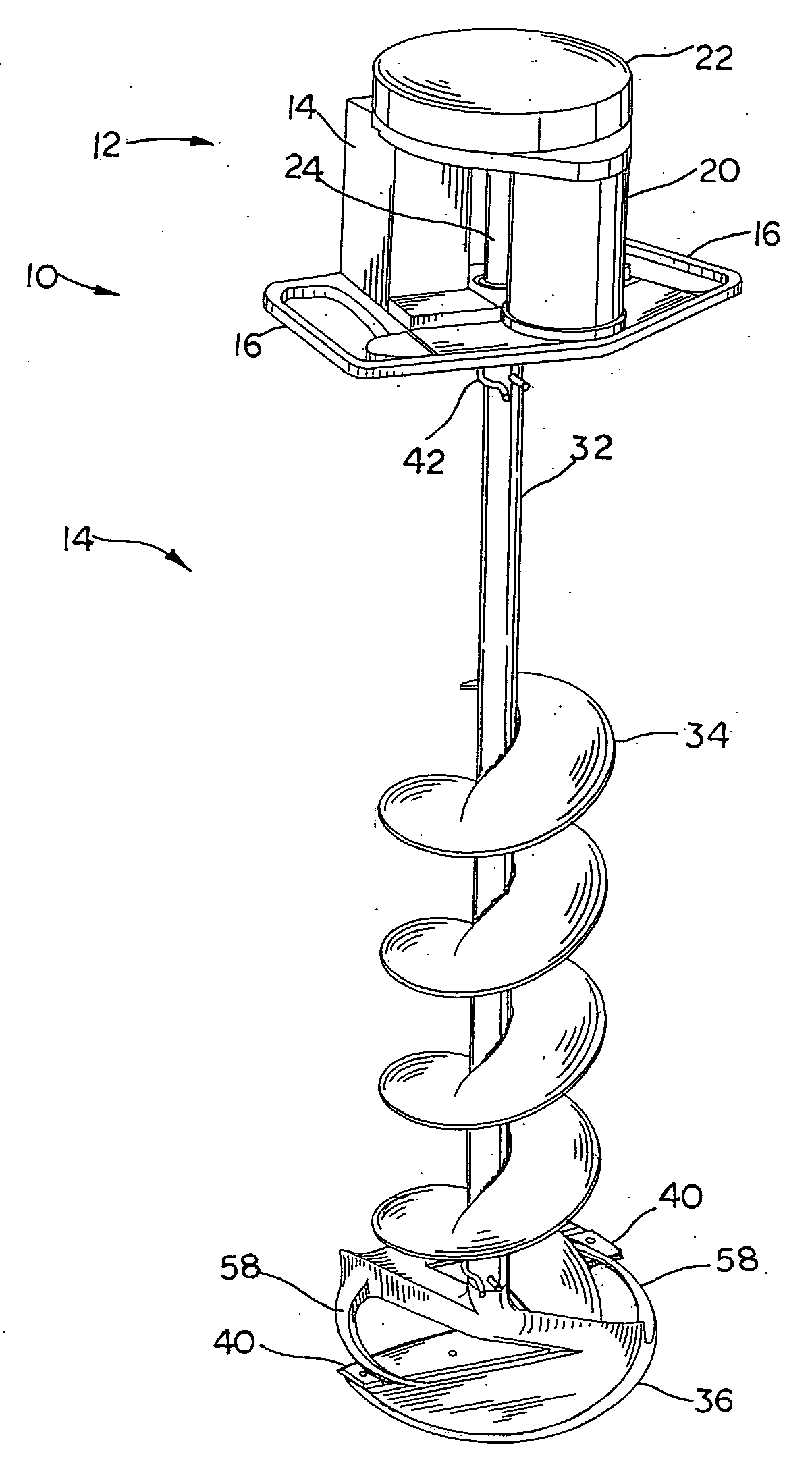
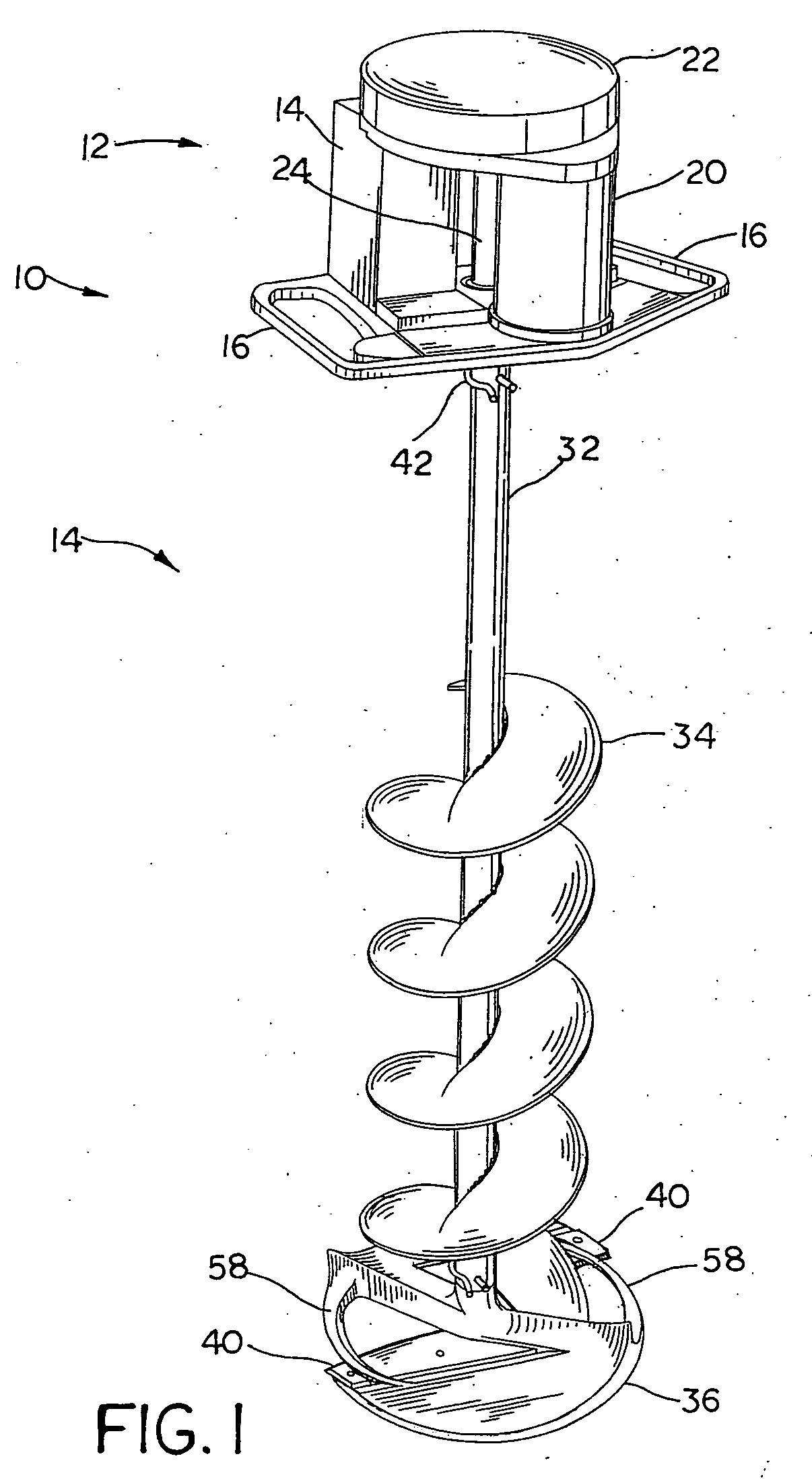
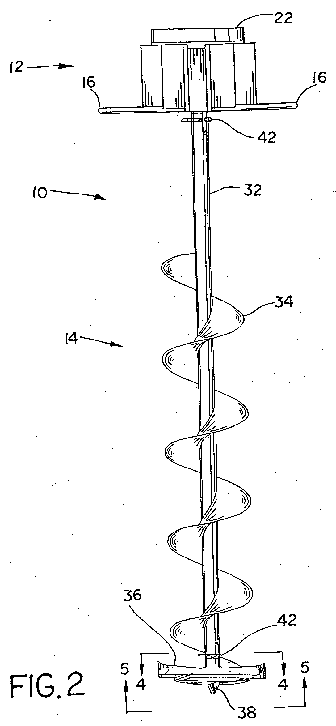
[0026] Referring now to the drawings, and more particularly to FIGS. 1-3, there is shown an ice cutting apparatus 10 including a drive unit 12 and a cutter unit 14. Drive unit 12 includes handles 16, batteries 18, a motor 20, a gear housing 22 and a shaft 24. Handles 16 are oriented so that the user can easily lift and operate ice cutting apparatus 10 and to prevent the rotation of drive unit 12 so as to allow drive unit 12 to rotate shaft 24 for the driving of cutter unit 14. Batteries 12 are oriented to balance the weight of motor 20 on alternate sides of shaft 24. Advantageously, the placing of batteries 18 and motor 20 balance the weight that is supported by way of shaft 24 when ice cutting apparatus 10 is in operation. Gear housing 22 encloses a gear, not shown, that is driven from motor 20 and is attached to shaft 24.

[0027] Shaft 24 includes a groove 26, O-rings 28 and a hole 30. Groove 26 interacts with a roll pin located in shaft 32 of cutter unit 14. O-rings 28 are situate...


PUM


Abstract

An ice cutting apparatus including a driving mechanism, a shaft, a plate, a web and a blade. The shaft is connected to the driving mechanism. The plate has at least one opening therein, the plate being detachably connected to the shaft. The web borders a portion of the at least one opening. The blade is attached to the plate, and is shaped to accommodate the web.

Description

CROSS REFERENCE TO RELATED APPLICATIONS [0001] This is a non-provisional application based upon U.S. provisional patent application Ser. No. 60 / 680,162, entitled “ICE CUTTER”, filed May 12, 2005.BACKGROUND OF THE INVENTION [0002] 1. Field of the Invention [0003] The present invention relates to an ice cutting device, and, more particularly, an ice cutting device for use by ice fishermen. [0004] 2. Description of the Related Art [0005] The catching of fish utilizing bait on a concealed hook is a practice that goes back before recorded history. Fishing in winter time can be rather arduous and requires making a hole through the ice in order to use the baited hook to attract fish thereto. Ice fishermen have utilized various techniques include chopping holes through the ice and utilizing powered augers to drill holes through the ice. A powered auger may also be utilized for drilling holes in the ground for the placing of fence posts therein. The unit consists of an auger device that is p...

Claims


Application Information

Patent Timeline
Patent Type & Authority Applications(United States)
IPC IPC(8): F25C5/04
CPCA01K97/01F25C5/04E21B7/008
Inventor PEPPLE, GREGORY A.
Owner PAVATI ENG
Why Eureka
Try Eureka