Grate for efficiently burning fuel

a fuel efficient and grating technology, applied in the direction of domestic stoves or ranges, ways, lighting and heating apparatus, etc., can solve the problems of inconvenient chopping of one's own wood, inability to efficiently burn fuel, and difficulty in obtaining wood, so as to achieve efficient burning of fuel

Inactive Publication Date: 2006-11-23
HATA RICHARD
View PDF9 Cites 4 Cited by
  • Summary
  • Abstract
  • Description
  • Claims
  • Application Information

AI Technical Summary

Benefits of technology

[0010] The present invention is directed to a grate for efficiently burning fuel, comprising a plurality of interconnected plate members, at least one stabilizing bar connected to at least two of the plurality of interconnected plate members, a collection plate situated between at least two of the plurality of interconnected plate members, and at least one support member connected to at least one of said plurality of interconnected plate members wherein the plurality of interconnected plate members are joined together on at least one side.

Problems solved by technology

The expense of firewood, the inconvenience of chopping one's own wood, and retrieving wood when the fire burns down too quickly are some drawbacks of wood burning fireplaces.
Further, when burning wood, the combustion of the wood is often incomplete and large pieces of unburned wood fall below the grate and remain unburned.
Fireplace grate designs employed historically fail to provide safety features and efficiency characteristics.
Overlooking such design features and benefits evidences a disadvantage in that older fireplace designs can not meet today's standards regarding fuel efficiency, as demanded by the ever increasing cost of non-renewable fuels, and regulations related to fireplace safety.

Method used


Image

  • Grate for efficiently burning fuel
  • Grate for efficiently burning fuel
  • Grate for efficiently burning fuel

Examples


Embodiment Construction

[0015] It is to be understood that the figures and descriptions of the present invention have been simplified to illustrate elements that are relevant for a clear understanding of the present invention, while eliminating, for purposes of clarity, many other elements found in typical fuel burning grates. Those of ordinary skill in the art will recognize that other elements are desirable and / or required in order to implement the present invention. However, because such elements are well known in the art, and because they do not facilitate a better understanding of the present invention, a discussion of such elements is not provided herein.

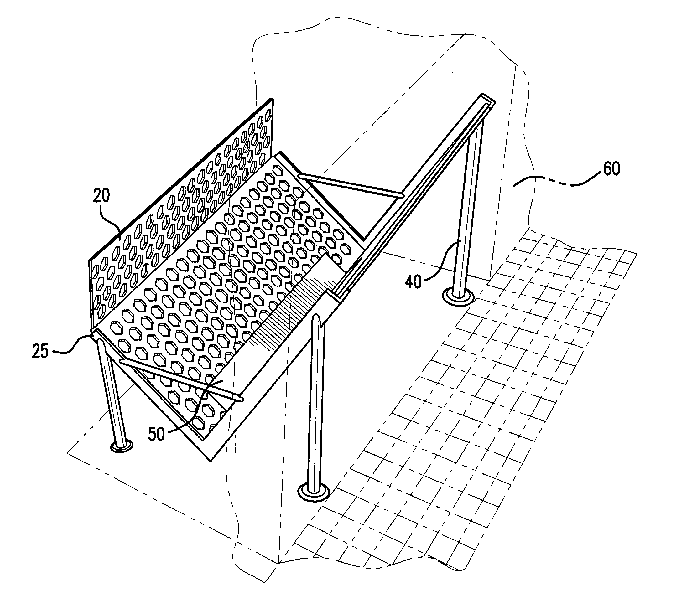
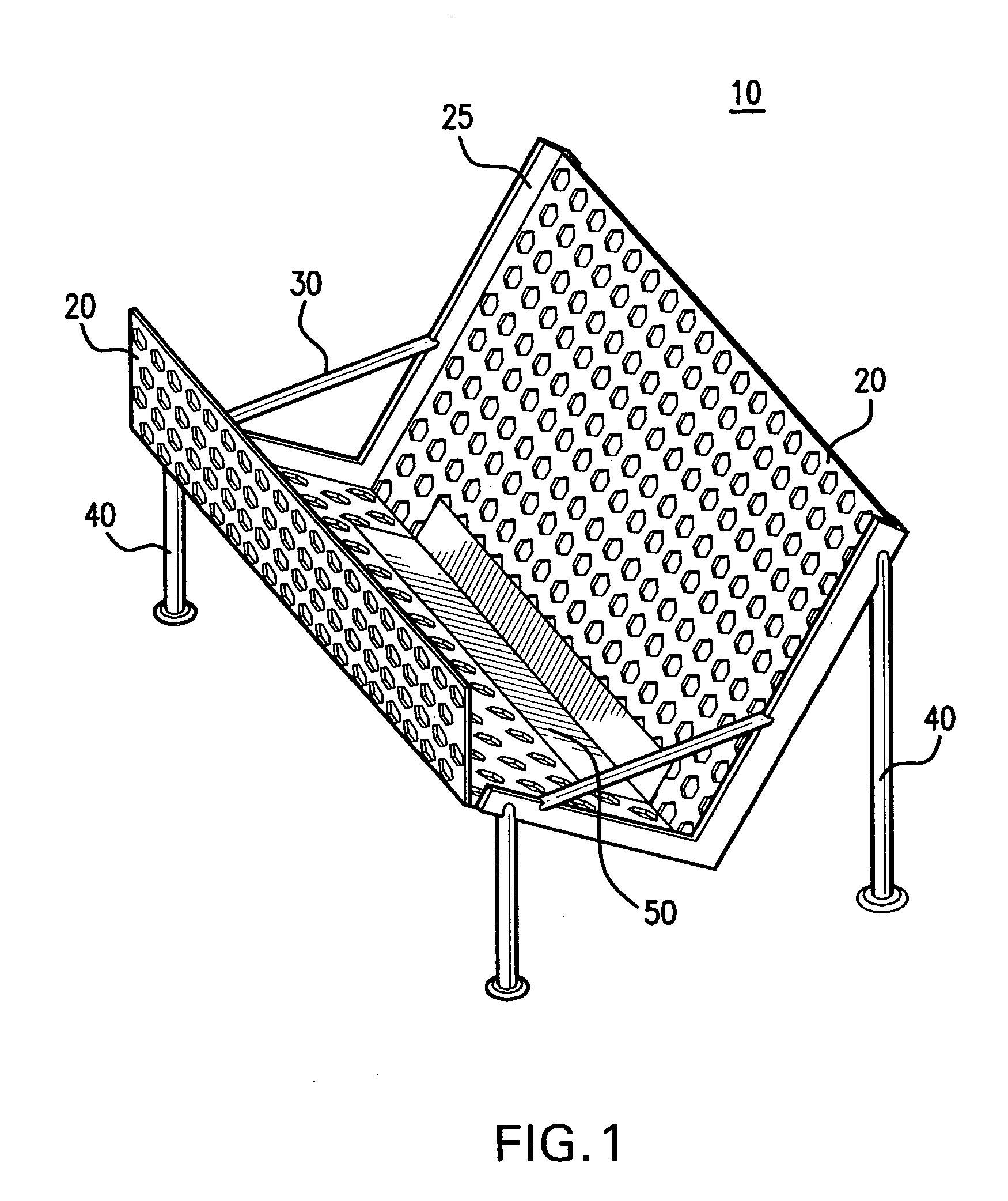
[0016]FIG. 1 is an isometric diagram illustrating a grate for efficiently burning fuel. The grate includes a plurality of interconnected plate members 20, at least one stabilizing bar 30 connected to at least two said plurality of interconnected plate members 20, a collection plate 50 situated between at least two of the plurality of interconnected ...


PUM


Abstract

A grate for efficiently burning fuel is disclosed. The grate for efficiently burning fuel includes a plurality of interconnected plate members, at least one stabilizing bar connected to at least two of the plurality of interconnected plate members, a collection plate situated between at least two of the plurality of interconnected plate members and at least one support member connected to at least one of the plurality of interconnected plate members, wherein the plurality of interconnected plate members are joined together on at least one side.

Description

CROSS REFERENCE TO RELATED APPLICATIONS [0001] This application claims priority to U.S. Patent Application Ser. No. 60 / 684,240 entitled “A Grate For Efficiently Burning Fuel,” filed May 23, 2005, which application is hereby incorporated by reference herein as if set forth in the entirety:STATEMENT REGARDING FEDERALLY SPONSORED RESEARCH OR DEVELOPMENT [0002] Not Applicable. BACKGROUND OF THE INVENTION [0003] 1. Field of the Invention [0004] The present invention is directed generally to a method and apparatus for supporting solid fuel sources and, more particularly, to a grate for efficiently burning fuel. [0005] 2. Description of the Background [0006] Historically, fuel burning grates have been designed to maximize the size of fuel to be burned and to minimize manufacturing costs. Various forms of fireplace grates which include some of these general structural and operational features have been disclosed in U.S. Pat. Nos. 2,985,165, 3,771,511, 3,987,779, 4,161,168, and 4,215,671. [0...

Claims


Application Information

Patent Timeline
Patent Type & Authority Applications(United States)
IPC IPC(8): F24B1/193
CPCF24B1/193
Inventor HATA, RICHARD
Owner HATA RICHARD
Why Eureka
Try Eureka