Interspinous process implant with slide-in distraction piece and method of implantation

Inactive Publication Date: 2006-11-23
MEDTRONIC EURO SARL
View PDF99 Cites 164 Cited by
  • Summary
  • Abstract
  • Description
  • Claims
  • Application Information

AI Technical Summary

Problems solved by technology

Spinal stenosis results in a reduction foraminal area (i.e., the available space for the passage of nerves and blood vessels) which compresses the cervical nerve roots and causes radicular pain.
Another symptom of spinal

Method used


Image

  • Interspinous process implant with slide-in distraction piece and method of implantation
  • Interspinous process implant with slide-in distraction piece and method of implantation
  • Interspinous process implant with slide-in distraction piece and method of implantation

Examples


Embodiment Construction

[0046] Interspinous Implants

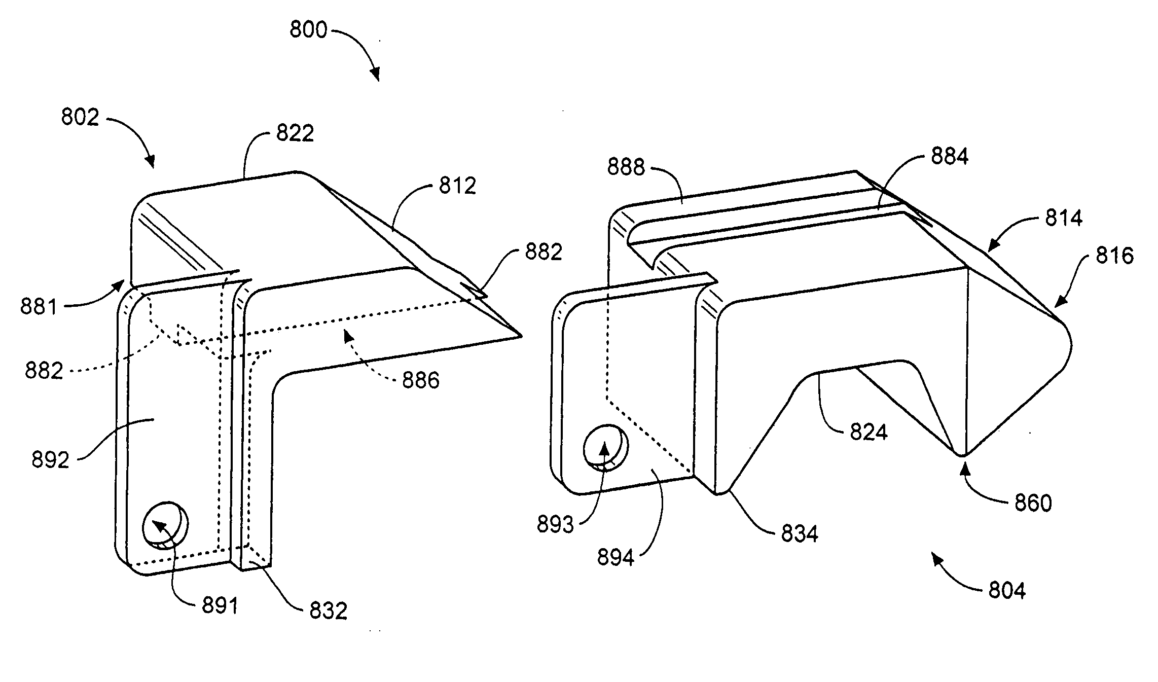
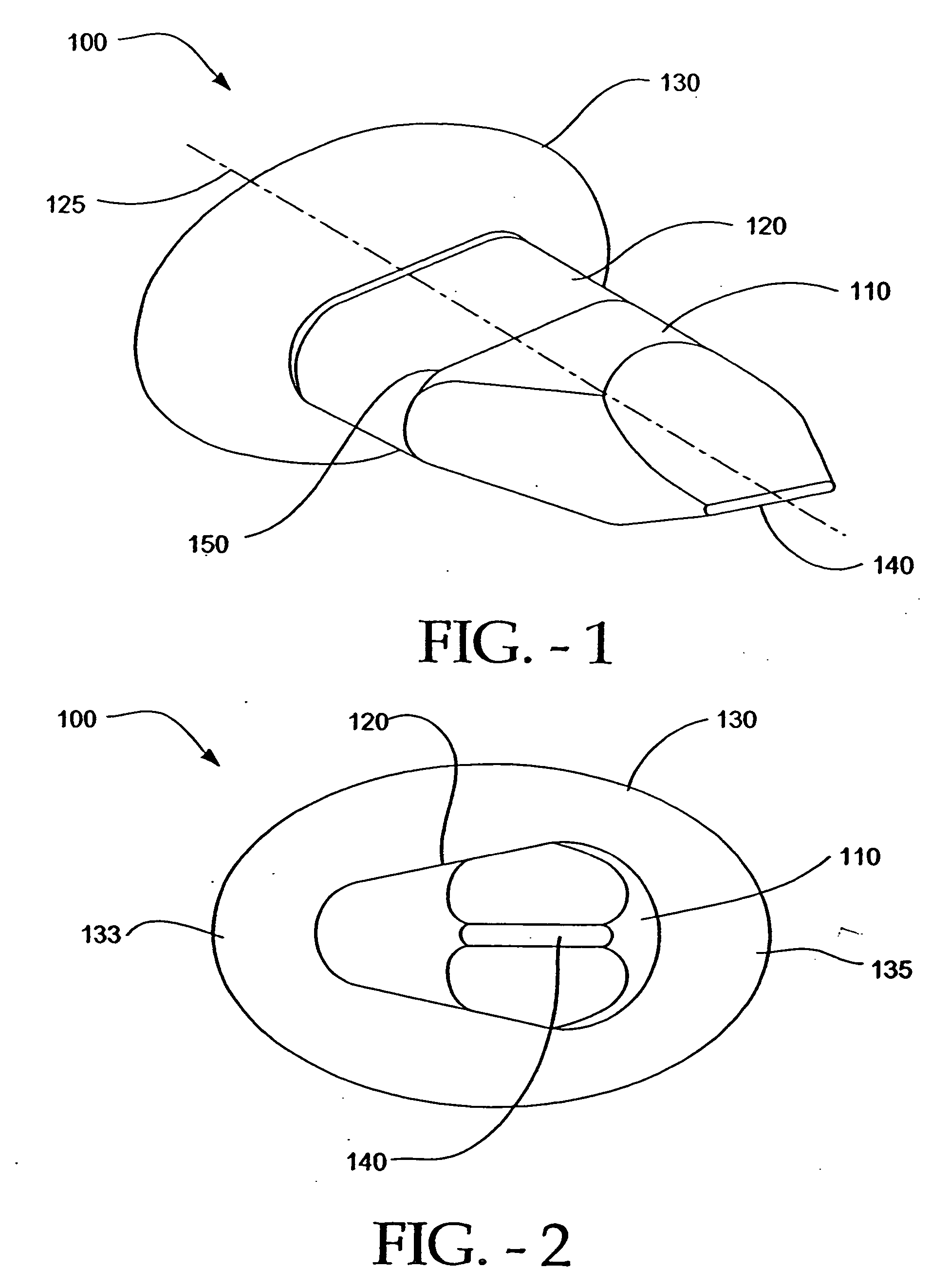
[0047]FIGS. 1 and 2 illustrate an implant 100 in accordance with an embodiment of the present invention. The implant 100 comprises a wing 130, a spacer 120, and a lead-in tissue expander (also referred to herein as a distraction guide) 110. The distraction guide 110 in this particular embodiment is wedge-shaped, i.e., the implant has an expanding cross-section from a distal end of the implant 102 to a region 104 where the guide 110 joins with the spacer 120 (referencing for the figures is based on the point of insertion of the implant between spinous processes). As such, the distraction guide functions to initiate distraction of the soft tissue and the spinous processes when the implant 100 is surgically inserted between the spinous processes. It is to be understood that the distraction guide 110 can be pointed and the like, in order to facilitate insertion of the implant 100 between the spinous processes of adjacent cervical vertebrae. It is advantageou...


PUM


Abstract

Systems and method in accordance with embodiments of the present invention can includes an implant having an initiating piece and a distraction piece. The initiating piece can include a lower distraction element, a second wing, a lower portion of a spacer, and a lower portion of a first wing. The initiating piece can be positioned such that an interspinous ligament of the targeted motion segment is disposed between the first and second wing. The distraction piece can include an upper distraction element, an upper portion of the spacer, and an upper portion of the first wing, and can be mated with the initiating piece by mating a rail of the distraction piece with a slot of the initiating piece, thereby disposing the implant between adjacent spinous processes.

Description

CLAIM OF PRIORITY [0001] This application claims priority to U.S. Provisional Application No. 60 / 664,311 entitled INTERSPINOUS PROCESS IMPLANT WITH SLIDE-IN DISTRACTION PIECE AND METHOD OF IMPLANTATION, by Zucherman et al., filed Mar. 22, 2005, (Attorney Docket No. KLYC-1087US5) and is a continuation-in-part of U.S. patent application Ser. No. 10 / 850,267 entitled DISTRACTIBLE INTERSPINOUS PROCESS IMPLANT AND METHOD OF IMPLANTATION, by Zucherman et al., filed May 20, 2004 (Attorney Docket No. KLYC-01087US2), which claims priority to U.S. Provisional Patent Application No. 60 / 472,817 entitled CERVICAL INTERSPINOUS PROCESS DISTRACTION IMPLANT AND METHOD OF IMPLANTATION, by Zucherman et al., filed May 22, 2003, (Attorney Docket No. KLYC-01087US0). CROSS-REFERENCE TO RELATED APPLICATIONS [0002] This U.S. Patent Application incorporates by reference all of the following co-pending applications and issued patents: [0003] U.S. Patent Application Serial No. 60 / 664,049, entitled “Interspinous...

Claims


Application Information

Patent Timeline
IPC IPC(8): A61F2/44
CPCA61B17/7068A61B17/56
Inventor ZUCHERMAN, JAMES F.HSU, KEN Y.KLYCE, HENRYWINSLOW, CHARLES J.YERBY, SCOTT A.FLYNN, JOHN J.MITCHELL, STEVEN T.MARKWART, JOHN A.
Owner MEDTRONIC EURO SARL
Why Eureka
Try Eureka