Linked slideable and interlockable rotatable components

a technology of rotatable components and interlocking parts, which is applied in the field of linked slideable and interlockable rotatable components, can solve the problems of increased trauma, longer healing time, and higher risk of complications, and achieves the effects of reducing the potential for slippage or other instability of the delivered device, facilitating the ability of the device, and reducing the potential for slippage or other instability

Inactive Publication Date: 2006-08-24
MORPHOGENY
View PDF42 Cites 254 Cited by
  • Summary
  • Abstract
  • Description
  • Claims
  • Application Information

AI Technical Summary

Benefits of technology

[0015] The rotatable components could be designed so that each component has a pair of slotted openings, preferably in the form of a first elongate, centrally disposed slot extending between the distal end of the rotatable component and approximately a mid-point of the component, and a second elongate, centrally connected, symmetrically mirrored (with respect to a diagonal plane bisecting the linkable segment) slot extending between a proximal end of the rotatable component and approximately the mid-point of the component. The two slots overlap one another at each of two bores running the length and height of the rotatable component. The second elongate slot extends in an opposite direction from the first elongate slot. This pair of slotted openings allows the component guide to remain tethered within the body of the rotatable component. This slot configuration allows the rotation of the rotatable component with the component guide therein, without undesired movement of the component guide. Where the components have more than one component guide member, at least a pair of slotted openings would be provided for each guide member. As a result, the rotatable components may achieve greater distraction of the space than existing methods can provide through minimal invasive surgical techniques.
[0016] A rotatable component of this disclosure can also include a male member on its side that allows the component to interlock into a female opening in an adjacent component. The components might also have depressed tracks along the sides on the top of the components with a corresponding rail on the bottom of the adjacent component that allows for further interlocking and stability of the device upon rotation of respective components to their second orientation relative to the component guide.
[0017] One benefit of utilizing the rotatable components of the present disclosure as an implant is that separate distraction instruments are not required to pre-distract adjacent tissue such as vertebras surrounding an interbody space. One or more rotatable components are delivered in a first, e.g. horizontal, orientation, and only rotated to a vertical (or other) orientation upon delivery to a location at which no pre-distraction for the placement of the components as an implant is necessary since the rotatable components would accomplish any necessary distraction themselves as a result of the rotation. In addition, the device could be used as a distraction instrument itself, and removed after the desired treatment is completed. For example, the placement of a hydrogel nucleus replacement device could be delivered through smaller MIS access procedures by utilizing the disclosed device as a distraction instrument. The device could also be useful where a smaller size portal entry through tissue such as the annulus is desired but limited due to the vertical height of the implant itself. By delivering one or more of the components horizontally and then rotating and assembling the implant within the interbody space the smaller portal entry can be achieved while maintaining the full desired vertical height of the construct. This aspect of the present disclosure would be advantageous anywhere that a minimal entry portal is desired even where no distraction of tissue is needed and the height of the desired implant is equal to or less than the height of the tissue space that the device is being implanted in, such as the interbody space between the vertebra.
[0018] Another advantage is that the components can be delivered in a manner that allows them to precisely follow the curvature of the inside of the annulus wall. Alternative designs of the components would facilitate the ability of the device to form a precise arc. They also can have various vertical heights to allow the precise desired distraction of the inter-body space without changing the portal opening size. Also, unlike other methods such as disclosed in Johnson, the rotatable components described stack horizontally rather than vertically. This horizontal stacking provides optimal transfer of load through each component itself rather than a composite of components like in Johnson, thereby substantially reducing the potential for slippage or other instability of the delivered device. In some applications each rotatable component might support its own load bearing eliminating the need for stacking altogether. Some applications may only require one rotatable component to accomplish the desired medical result of distraction and / or implantation of a permanent device whether it is the disclosed device or another device. Rotatable components can be delivered in straight lines, curved lines, or in a 360° circle within or around the inside of the annulus wall.
[0019] The shape of the rotatable components can vary and can, by way of example, have a cross-sectional shape (where the cross-section is taken through a plane perpendicular to the longitudinal axis of the implant component) which is rectangular, oval, oblong, hexagonal, octagonal, or other multi-faceted shape. Also disclosed are alternative designs that include hinged components and ring designs which might further enhance the performance of the device. The rotatable components can also include a relief or cavity adjacent the two vertical ends to provide additional pressure (for fusion use) or flexibility (for nuclear replacement). This relief or cavity could also increase the load bearing surface area of the component resulting in a wider disbursement of load through the component.

Problems solved by technology

Traditional techniques utilize bulky instruments that necessitate large openings for entry and access into the area of treatment resulting in additional trauma, longer healing times, and higher risks of complications.
However, current distraction instrumentation limits the use of MIS techniques.
A similar problem exists with the delivery of existing implants themselves.
For example, in the area of treatment for degenerative disc disease there are several applications where the implantation of a device through MIS surgical techniques is strongly desired, but not feasible due to the entry portal size being determined by the size of the implant.
Thus, for example, current implantations of artificial discs, nucleus replacement, or interbody fusion devices require the removal of a large portion of the annulus, resulting in an increased likelihood of movement or displacement of the device from the desired location within the interbody space.
These methods, however, show high failure rates due to the inability to stabilize the site sufficient for successful fusion to occur.
The Stone implant has limited capabilities for distraction within the interbody space and the size of the opening in the annulus wall must coincide with the vertical height of the implant.
While they are connected and have interlocking features, any vertically stacked composite of components has a greater potential for instability within the interbody space.
Since it is necessary to minimize movement between vertebras with interbody fusion techniques, any instability due to such vertical stacking is unacceptable for effective use in an intervertebral space.

Method used


Image

  • Linked slideable and interlockable rotatable components
  • Linked slideable and interlockable rotatable components
  • Linked slideable and interlockable rotatable components

Examples


Embodiment Construction

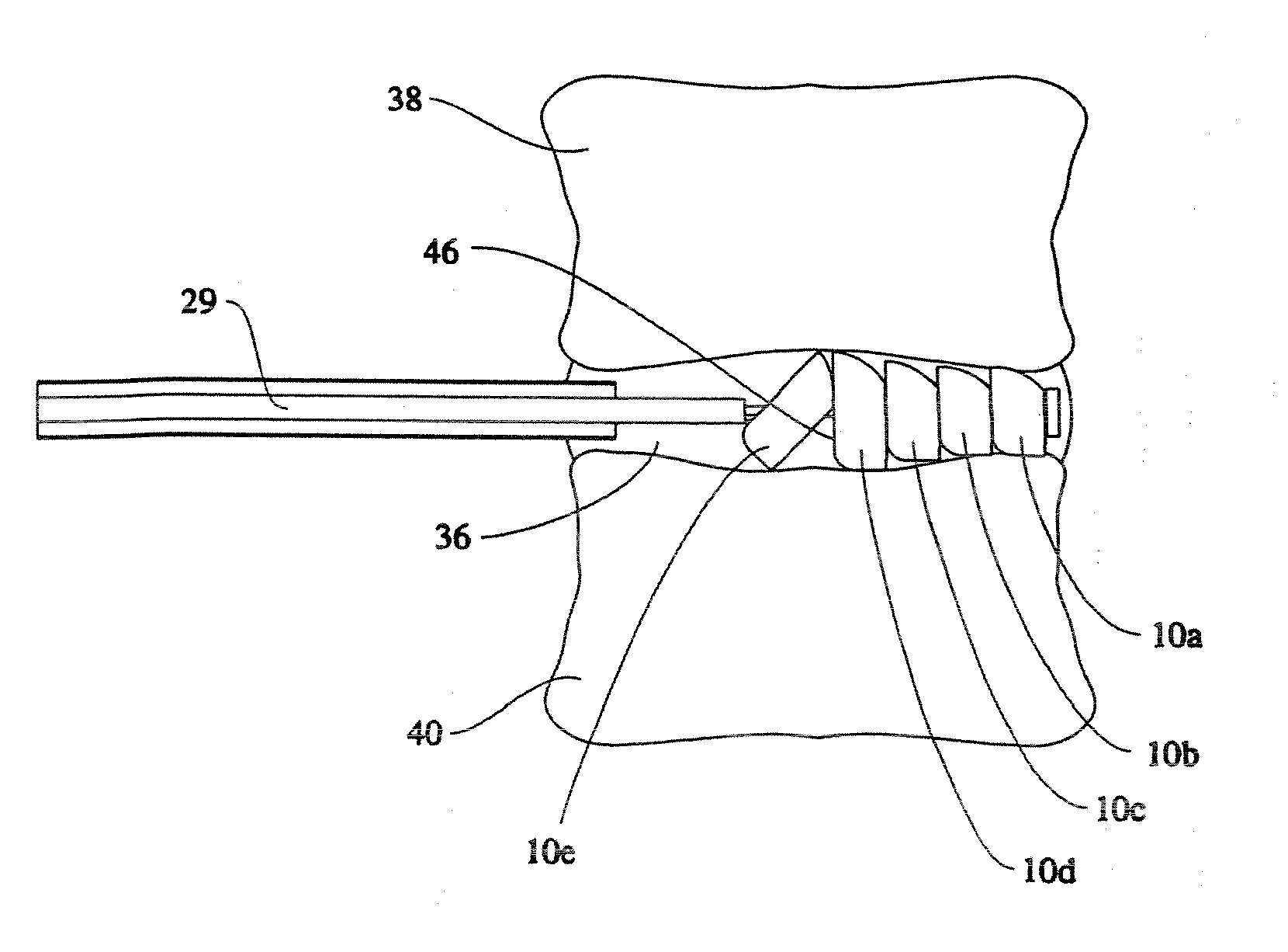
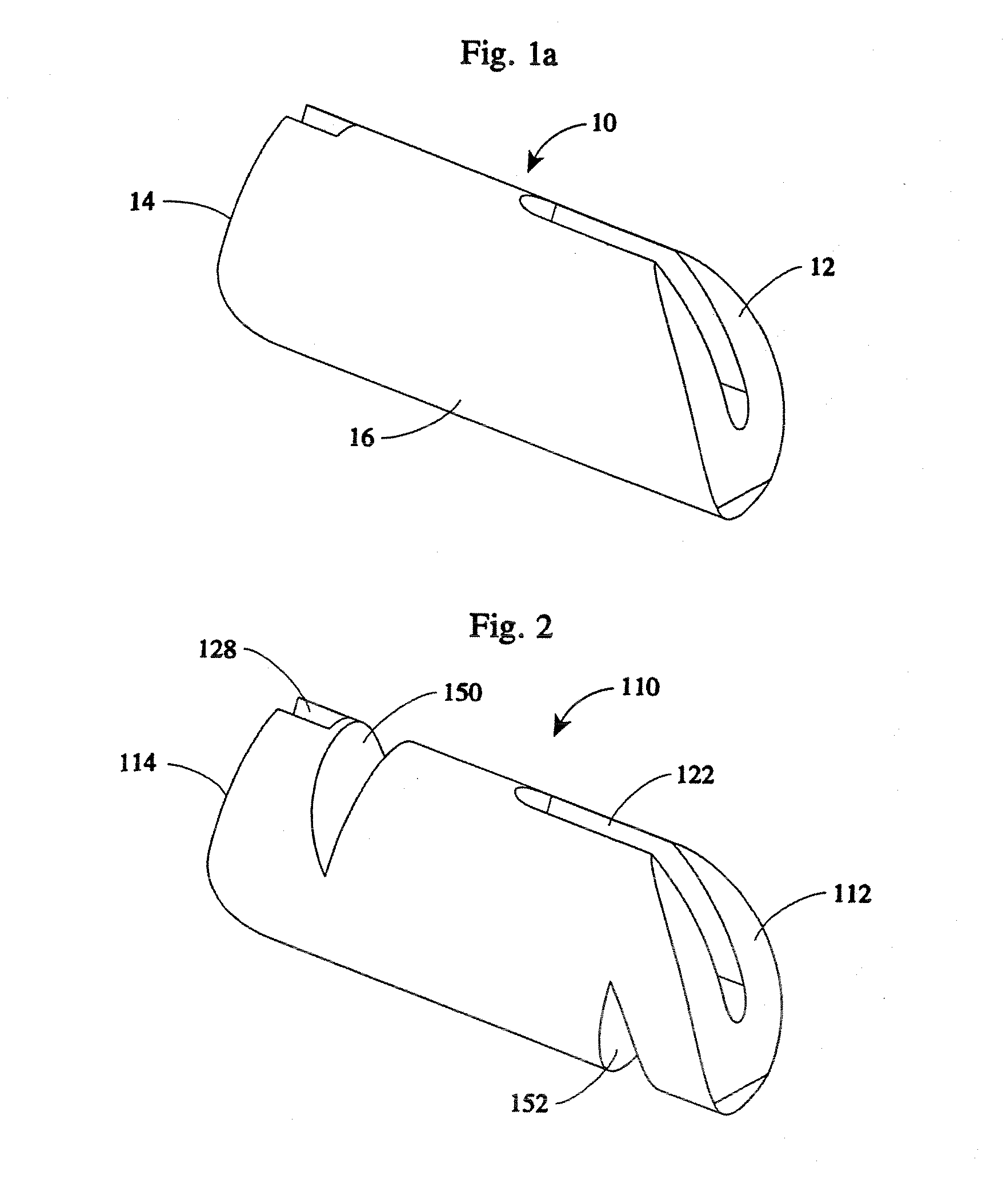
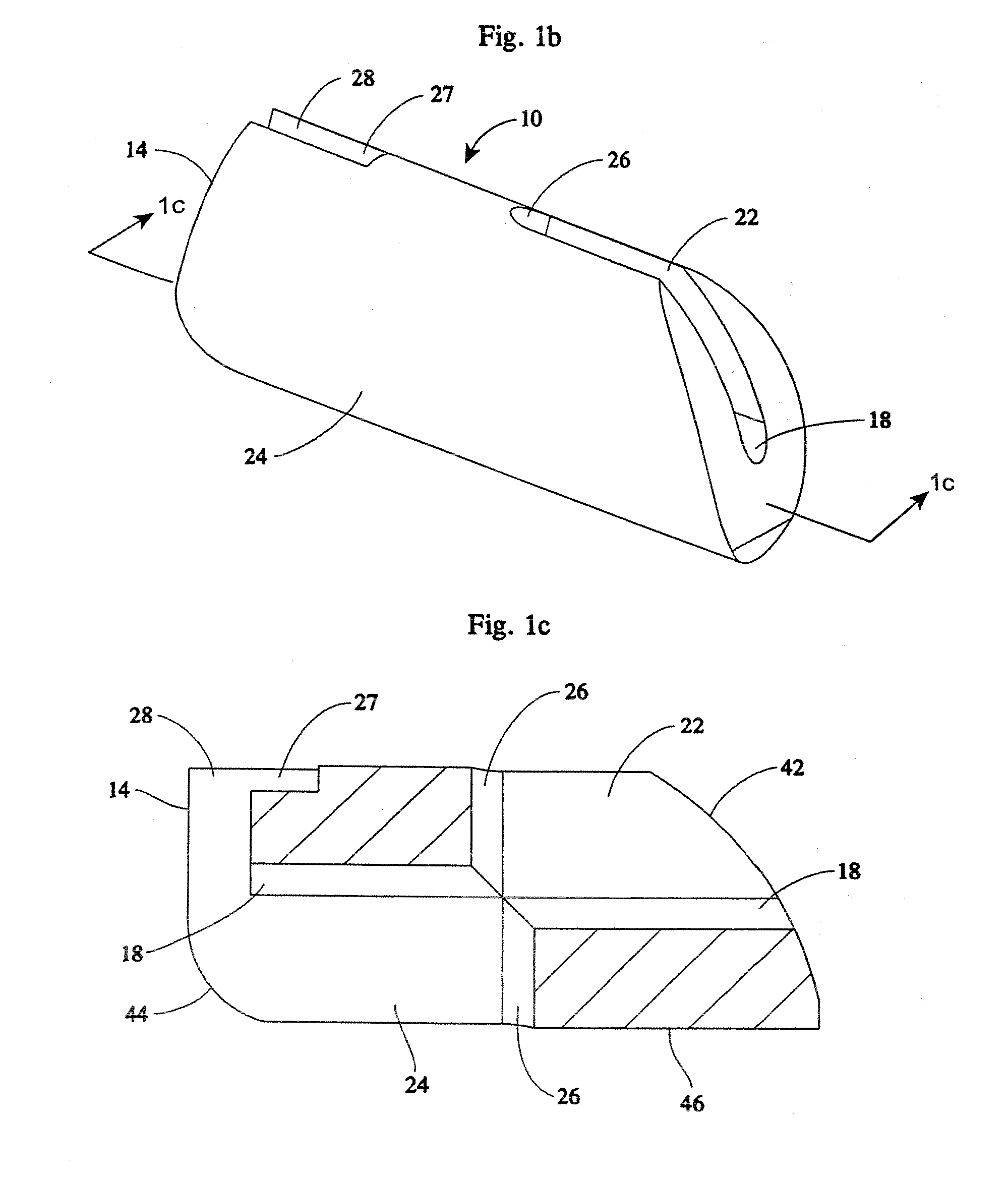
[0062] An implant system of the present disclosure includes a plurality of rotatable segments 10 of a first embodiment, as shown in FIGS. 1a-b, 4b-k, and 10. Each rotatable segment 10 has a leading or distal end 12, a trailing or proximal end 14, and a main body 16. A first hollow bore 18 extends the length of the rotatable segment 10, i.e. the hollow bore 18 extends from the leading or distal end 12, through to the trailing or proximal end 14.

[0063] The first hollow bore 18 is sized to accommodate a component guide 20 such that the rotatable segment 10 may be advanced along the component guide 20. For reasons explained below, the rotatable segment 10 also includes a first slotted opening 22 and a second slotted opening 24. The first and second slotted openings 22, 24 are contiguous with the hollow bore 18. The first slotted opening 22 extends between the distal end 12 and a second hollow bore 26. The second hollow bore 26 extends the horizontal height (i.e., the height when in the...


PUM

PropertyMeasurementUnit
heightaaaaaaaaaa
heightaaaaaaaaaa
thicknessaaaaaaaaaa

Abstract

Medical devices having one or more rotatable linkable components or segments, delivered in a first orientation relative to a component guide into a tissue cavity, such as the interbody vertebral space. After delivery, each segment may be rotated to a second, different orientation relative to the component guide, such as into a permanent vertical standing position. The segments achieve maximum distraction of the cavity space such as adjacent vertebra end plates, while using a minimal invasive surgical (MIS) approach. When the segments are tightened in place, the device provides long-term stability. The device can be used as a distraction instrument and/or permanent implant that can be used for interbody fusion, nuclear replacement, or anywhere in the body where a stable distraction of tissue and/or the implantation of material such as a device with an MIS approach is desired.

Description

REFERENCE TO RELATED APPLICATIONS [0001] This disclosure is entitled to the benefit of the filing date of U.S. Provisional Application No. 60 / 656,029, filed Feb. 24, 2005, as to all subject matter commonly disclosed therein.FIELD OF THE DISCLOSURE [0002] The device and method described herein include rotatable components or segments, delivered in a first orientation relative to a component guide, e.g. horizontally, into a tissue space such as the interbody vertebral space that, after delivery, rotate to a second, different orientation relative to the component guide, such as into a permanent vertical standing position. This allows for maximum distraction of the cavity space such as adjacent vertebra end plates, while using a minimal invasive surgical (MIS) approach. The device is able to be tightened with the method described below providing long-term stability. The device can be used as a distraction instrument and / or permanent implant that can be used for interbody fusion, nuclear...

Claims


Application Information

Patent Timeline
Patent Type & Authority Applications(United States)
IPC IPC(8): A61B17/88A61F2/44
CPCA61F2/28A61F2/442A61F2/4455A61F2/4611A61F2002/2817A61F2002/2835A61F2002/30062A61F2002/3008A61F2002/302A61F2002/30331A61F2002/30462A61F2002/30471A61F2002/30579A61F2002/30594A61F2002/30599A61F2002/30604A61F2002/30616A61F2002/30904A61F2002/4415A61F2002/448A61F2002/4627A61F2210/0004A61F2220/0033A61F2220/0075A61F2220/0091A61F2230/0065A61F2250/0063A61F2250/0098A61F2310/00017A61F2310/00023A61F2310/00029A61F2310/00113A61F2310/00131A61F2310/00149A61F2310/00155A61F2310/00161A61F2310/00203A61F2310/00263A61F2310/00269A61F2310/00281A61F2310/00293A61F2310/00365A61F2310/00359
Inventor ZWIRKOSKI, PAUL
Owner MORPHOGENY
Why Eureka
Try Eureka