

Cervical interspinous process distraction implant and method of implantation
a technology of cervical interspinous and implant, which is applied in the field of cervical interspinous process implant, can solve the problems of radicular pain, neck pain and muscle weakness, and and achieves the effect of reducing the foraminal area and reducing the pain of the radicula
- Summary
- Abstract
- Description
- Claims
- Application Information
AI Technical Summary
Problems solved by technology
Method used
Image

Examples
embodiment 100
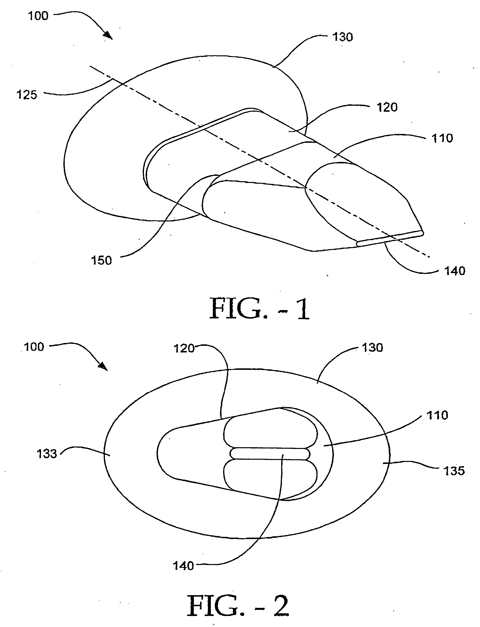
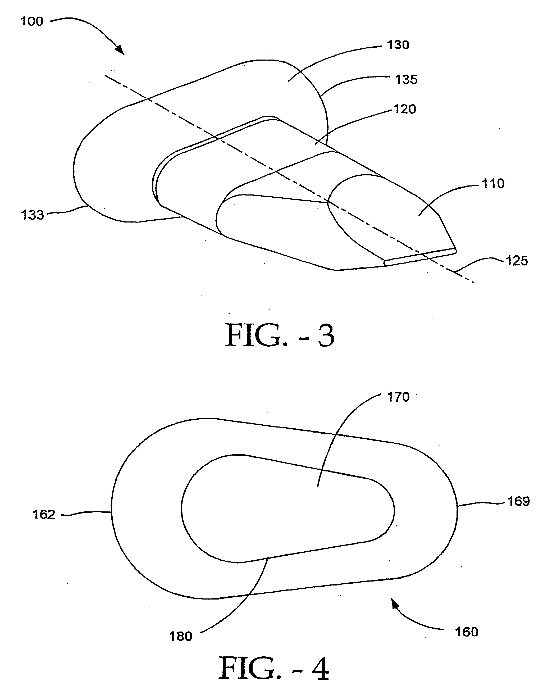
[0037] Additionally, as depicted in FIGS. 1 and 2, the wing 130 in this embodiment 100 is elliptically-shaped in a cross-section perpendicular to the longitudinal axis 125 of the spacer and distraction guide. As illustrated in the embodiment of FIG. 3, and as discussed in more detail herein, the wing 130 can have alternative shapes in cross-section, such as teardrop, wedge, circular, oval, ovoid, football-shaped, and rectangular-shaped with rounded corners and other shapes, and be within the spirit and scope of the invention. The wing 130 has an anterior portion 133 and a posterior portion 135.
[0038] Further, as also can be seen in FIGS. 1, 2, and 3 and other embodiments to be discussed herein, the spacer 120 is teardrop-shaped in cross-section perpendicular to the spacer's longitudinal axis 125. The spacer 120, like the wing 130, can have alternative shapes such as circular, wedge, oval, ovoid, football-shaped, and rectangular-shaped with rounded corners and other shapes, and be wi...
embodiment 300
[0044] The purpose of embodiment 300, as with the other embodiments, is to minimize the possibility of interference of implants positioned between the spinous processes of adjacent pairs of cervical vertebrae, e.g., implants between cervical vertebrae five and six, and between six and seven. During rotation of the neck, the spinous process move past each other in a scissor-like motion. Each cervical vertebra can rotate relative to the next adjacent cervical vertebra in the general range of about 6° -12°. It is to be understood that in addition, about 50 percent of the rotational movement of the neck is accomplished by the top two neck vertebrae. Thus, such embodiments can accommodate neck rotation without adjacent embodiments interfering with each other.
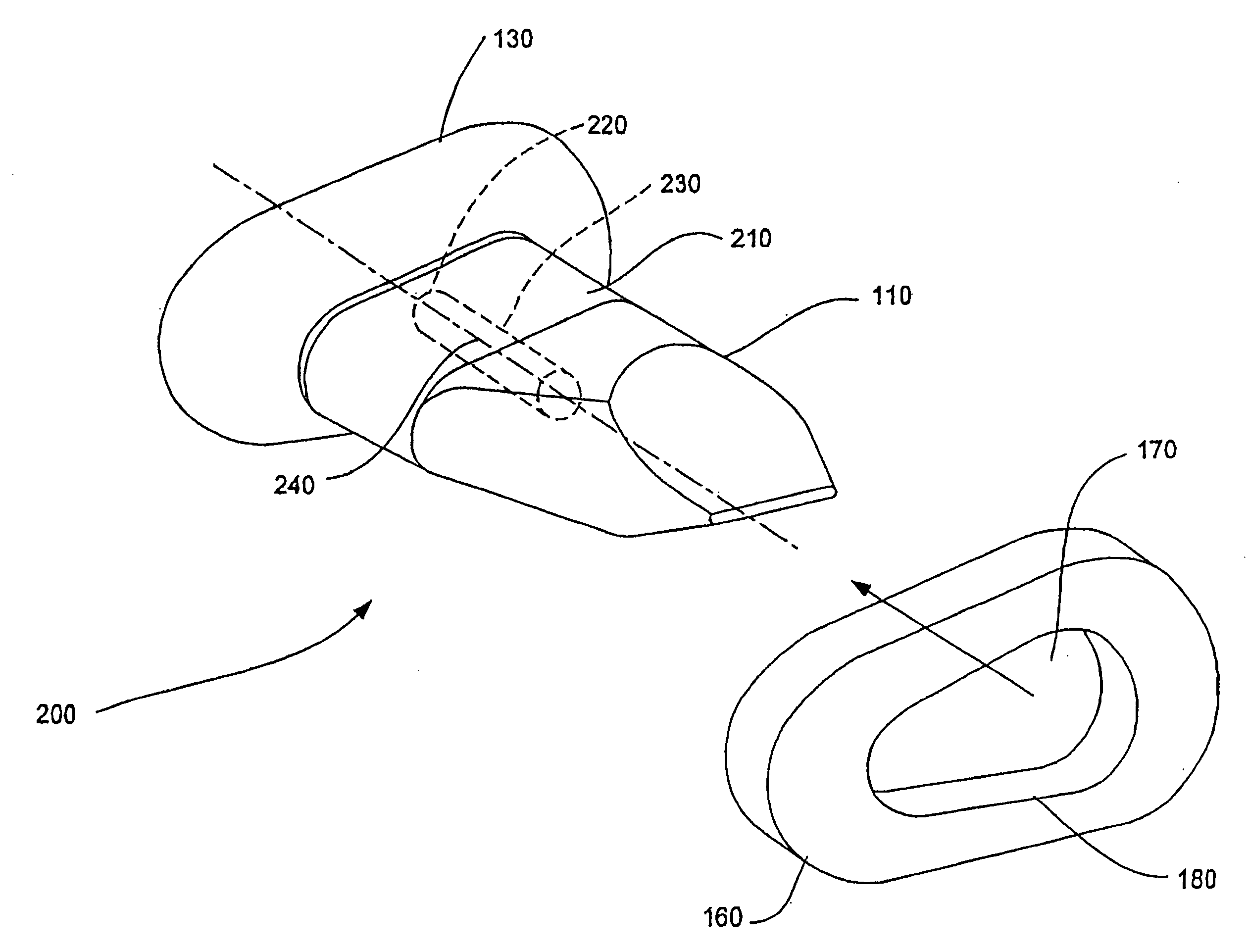
[0045] With respect to the prior embodiments which have first and second wings, the second wing 160, FIG. 4 can be designed to be interference-fit onto the spacer 120 or, in the case of a rotatable spacer 210, FIG. 5, a portion of th...
embodiment 400
[0046]FIGS. 10, 11, and 12 depict an embodiment 400 with a teardrop-shaped second wing 410 that has a bore 420 through a tongue 430 at the posterior end of the second wing 160. The bore on the second wing 420 is brought into alignment with a corresponding bore 440 on the spacer 120 when the second wing 160 is brought into position by surgical insertion relative to the rest of the implant. A threaded screw 450 is inserted through the aligned bores in a posterior-anterior direction to secure the second wing 160 to the spacer 120. The direction of insertion from a posterior to an anterior direction has the screw engaging the bores and the rest of the implant along a direction that is generally perpendicular to the longitudinal axis of the spacer 125 (FIGS. 1 and 3). This orientation is most convenient when the surgeon is required to use screw 450 to secure the second wing 160 to the rest of the implant. Other securing mechanisms using a member inserted into corresponding bores 420, 440...
PUM
 Abstract
Description
Claims
Application Information