Method for Displaying Catheter Electrode-Tissue Contact in Electro-Anatomic Mapping and Navigation System

a technology of electroanatomic mapping and navigation system, applied in the field of electrode catheters, can solve the problems of difficult to determine electrode-tissue contact, difficulty in ensuring adequate tissue contact between electrodes, and difficulty in detecting electrodes

Active Publication Date: 2008-11-20
ST JUDE MEDICAL ATRIAL FIBRILLATION DIV
View PDF30 Cites 255 Cited by
  • Summary
  • Abstract
  • Description
  • Claims
  • Application Information

AI Technical Summary

Benefits of technology

[0008]It has been recognized that it is desirable to provide an indication concerning electrode coupling with minimal distraction to the physician. This is particularly the case where the system is used not only for initially establishing a desired electrode position for a procedure, but also for monitoring electrode procedure during the procedure. This can be accomplished, in accordance with the present invention, by providing an indication via a monitor of the navigation system. In this manner, the physician can receive continuously or periodically (occasionally) updated electrode coupling information during a medical procedure while the physician's attention remains substantially fully directed to the medical procedure.
[0010]In accordance with a still further aspect of the present invention, an electrode catheter system is provided that allows for providing electrode coupling information with minimal distraction. An associated utility involves: an electrode adapted to apply electrical energy; a catheter for enabling the electrode to be remotely operated by a physician; guidance instrumentation for guiding the electrode relative to the physiological structure of a patient; and a processor for receiving signal information and determining a level of electrical coupling between the electrode and the patient. The guidance instrumentation includes at least a navigation system for use in monitoring a position of the electrode. The processor is further operative to control the navigation system to provide an indication of the level of electrode coupling. In this regard, the processor can distinguish between a least two different levels of electrode coupling. In one implementation, the processor can distinguish between multiple levels of electrode coupling, including a level indicating elevated coupling that may be associated with the potential for penetrating tissue of interest. Such penetration may be desired or undesired. In either event, an indication of such elevated coupling can be useful to a physician. The various levels of electrode coupling may be determined by any suitable technology. In one implementation, the levels are distinguished based on a phase angle analysis.

Problems solved by technology

Several difficulties may be encountered, however, when attempting to form lesions at specific locations using some existing ablation electrodes.
One such difficulty encountered with existing ablation electrodes is how to ensure adequate tissue contact and electrical coupling.
Electrode-tissue contact is not readily determined using conventional techniques such as fluoroscopy.
Such experience only comes with time, and may be quickly lost if the physician does not use the electrode catheter on a regular basis.
In addition, when forming lesions in a heart, the beating of the heart further complicates matters, making it difficult to determine and maintain sufficient contact pressure between the electrode and the tissue for a sufficient length of time to form a desired lesion.
If the contact between the electrode and the tissue cannot be properly maintained, a quality lesion is unlikely to be formed.
Similarly, information on electrical coupling between the electrode and the target tissue is not readily available a priori to determine how much ablative energy may be absorbed in the tissue during ablation.
Such experience may lead to deficiencies, inefficiencies and complications, such as inadequate lesion formation, premature high impedance shut-off, tissue charring, and thrombus formation.

Method used


Image

  • Method for Displaying Catheter Electrode-Tissue Contact in Electro-Anatomic Mapping and Navigation System
  • Method for Displaying Catheter Electrode-Tissue Contact in Electro-Anatomic Mapping and Navigation System
  • Method for Displaying Catheter Electrode-Tissue Contact in Electro-Anatomic Mapping and Navigation System

Examples


Embodiment Construction

[0042]The present invention relates to providing an indication regarding a condition of interest, e.g., a level of electrode coupling, to a physician via guidance instrumentation of an electrode catheter system. While such an indication may be provided in connection with various parameters of interest in connection with an electrode catheter procedure and, specifically, in connection with a variety of electrode coupling assessment technologies, certain advantage are achieved by using an assessment technology capable of accurately identifying multiple electrode coupling levels such as a phase angle technology. In the following description, certain phase angle-related technologies are first described. Thereafter, various mechanisms for outputting information to the physician are described in detail.

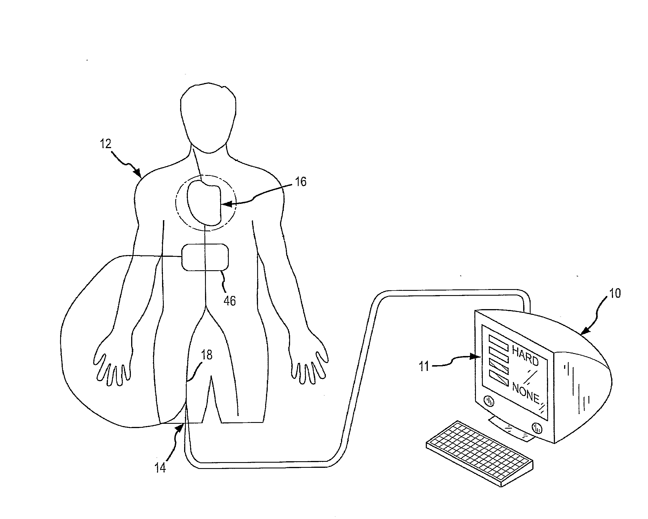
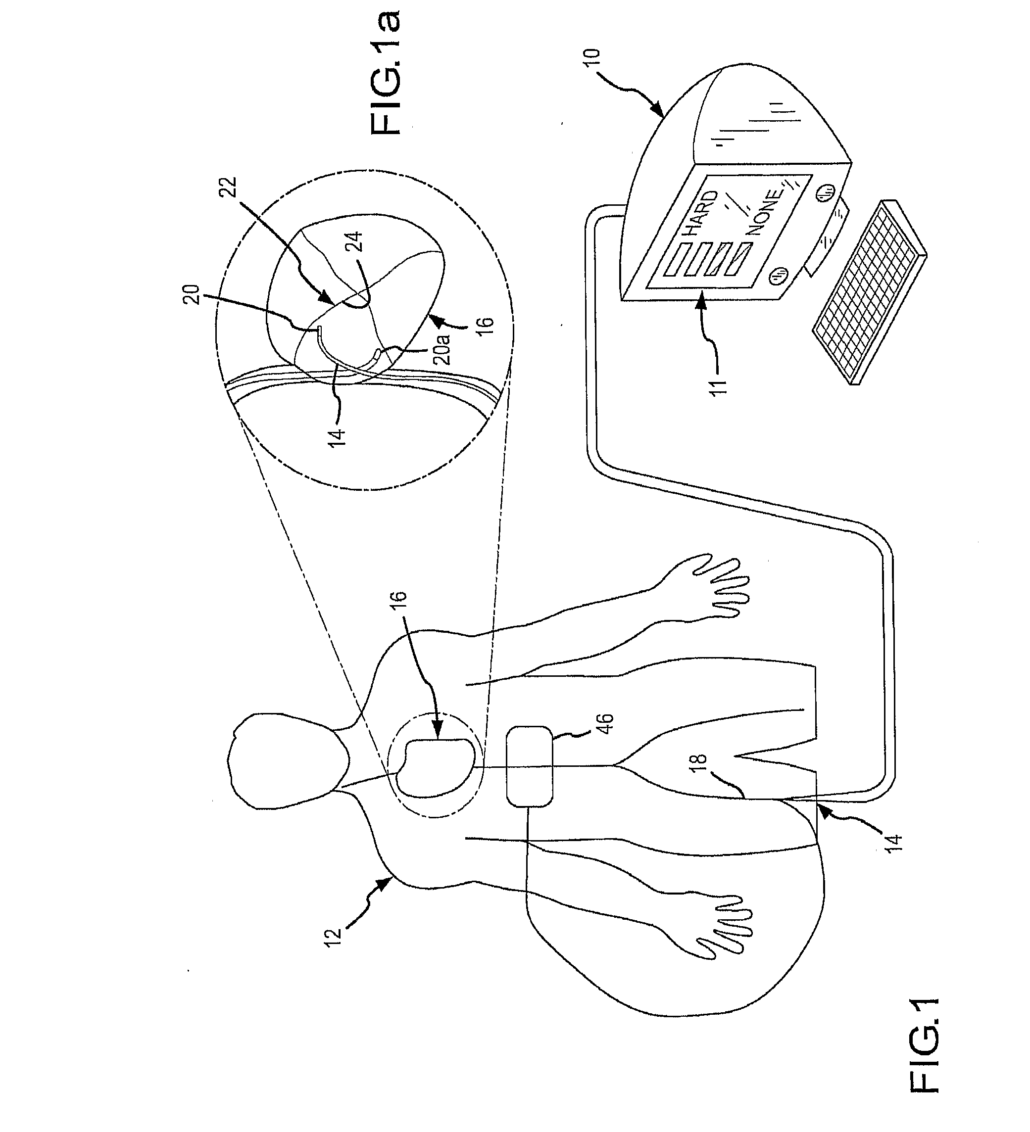
[0043]FIG. 1 is a diagrammatic illustration of an exemplary electrode catheter system 10 which may be implemented to assess electrode-tissue contact during a tissue ablation procedure for a...


PUM


Abstract

An electrode coupling output system associated with an electrode catheter that provides indication to the physician via the navigation system, concerning the electrical coupling of an electrode, such as an ablative or mapping electrode, with a patient. The indication may be provided by changing the color or other display characteristics of the electrode on the navigation system display or by way of providing a waveform indicating the electrode coupling. In this manner, electrode coupling information is provided to a physician in a manner that minimizes physician distraction.

Description

CROSS-REFERENCE TO RELATED APPLICATION[0001]This application claims the benefit of U.S. provisional application No. 60 / 748,234, filed on 6 Dec. 2006, which is incorporated herein by reference. This application is also related to international application docket no. 0B-047801WO, docket no. 0B-047809US, docket no. 0B-047810US, docket no. 0B-04781US, docket no. 0B-047812US, docket no. 0B-047814US and docket no. 0B-047815US, being filed concurrently herewith (“international applications”). The international applications are incorporated herein by reference.BACKGROUND OF THE INVENTION[0002]a. Field of the Invention[0003]The instant invention is directed toward an electrode catheter and a method for using the electrode catheter for tissue ablation. In particular, the electrode catheter of the present invention may comprise a circuit to assess electrode-tissue contact and electrical coupling for applying ablative energy (e.g., RF energy) to target tissue.[0004]b. Background Art[0005]It is ...

Claims


Application Information

Patent Timeline
Patent Type & Authority Applications(United States)
IPC IPC(8): A61N1/05A61B5/296
CPCA61B18/1492A61B2018/00666A61B2018/00357A61B2018/00702A61B2018/0075A61B2018/00755A61B2018/00869A61B2018/00875A61B2019/464A61B2019/465A61B18/1206A61B2018/00303A61B2018/00577A61B2018/00642A61B19/5244A61B34/20A61B2090/064A61B2090/065A61B5/053
Inventor PAUL, SAURAVCAO, HONG
Owner ST JUDE MEDICAL ATRIAL FIBRILLATION DIV
Why Eureka
Try Eureka