Adjustable Distraction Cage With Linked Locking Mechanisms

a technology of locking mechanism and distraction cage, which is applied in the field of expanding spinal implants, can solve the problems of inability to expand and distract the end plates or fix the devices, and existing static cages that cannot reliably improve the space for neural elements, so as to reduce size and diameter, effectively distract the intervertebral area, and reduce the effect of size and diameter

Active Publication Date: 2011-06-02
HOWMEDICA OSTEONICS CORP
View PDF100 Cites 257 Cited by
  • Summary
  • Abstract
  • Description
  • Claims
  • Application Information

AI Technical Summary

Benefits of technology

[0008]The invention is particularly directed to a spinal implant suitable for placement between superior and interior vertebral bodies. The spinal implant has a first member or top plate for engaging an end of the superior vertebral body and a second member or base for engaging an end of the inferior vertebral body and has one or more extendable support elements preferably with one or more top end plates that engage vertebral bodies in the expanded configuration. The one or more extendable support elements have a first contracted configuration to facilitate deployment of the implant between the superior and inferior vertebral bodies and safely past sensitive neural elements and a second or an extended configuration to engage the end plates of the vertebral bodies. The implant has a locking system with linked locking elements that mechanically engage or interlock with the extendable support element or the first member to lock the implant between the superior and inferior vertebral bodies in an expanded configuration.
[0017]The clinical goals of the implant and the method for its insertion provide a minimally invasive risk of trauma to nerve roots, reduce pain, improve function, and permit early mobilization of the patient after fusion surgery. The fixation elements maintain the implant in a desired position until healing (fusion or arthrodesis) occurs. At this point, the implant is incorporated inside bone and its role becomes quiescent.

Problems solved by technology

Existing devices for interbody stabilization have important and significant limitations, including inability to expand and distract the end plates or to fix the device in place to prevent relative movement between the device and an adjacent vertebral body.
Moreover, current interbody spacers do not maintain interbody lordosis and can contribute to the formation of a straight or even kyphotic segment and the clinical problem of “flatback syndrome.” Separation of vertebral end plates increases space available for the neural elements, specifically the neural foramen.
Existing static cages do not reliably improve space for the neural elements.
Conventional devices for intervertebral body stabilization include poor interface between bone and the biomaterial of the device.
That is, the ridges or coatings on the implant offer little resistance to movement applied to either side of the end plates.

Method used


Image

  • Adjustable Distraction Cage With Linked Locking Mechanisms
  • Adjustable Distraction Cage With Linked Locking Mechanisms
  • Adjustable Distraction Cage With Linked Locking Mechanisms

Examples


Embodiment Construction

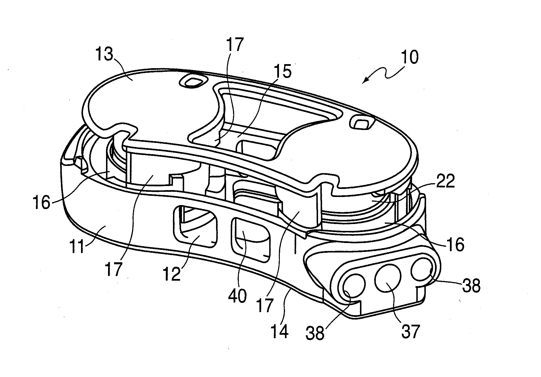
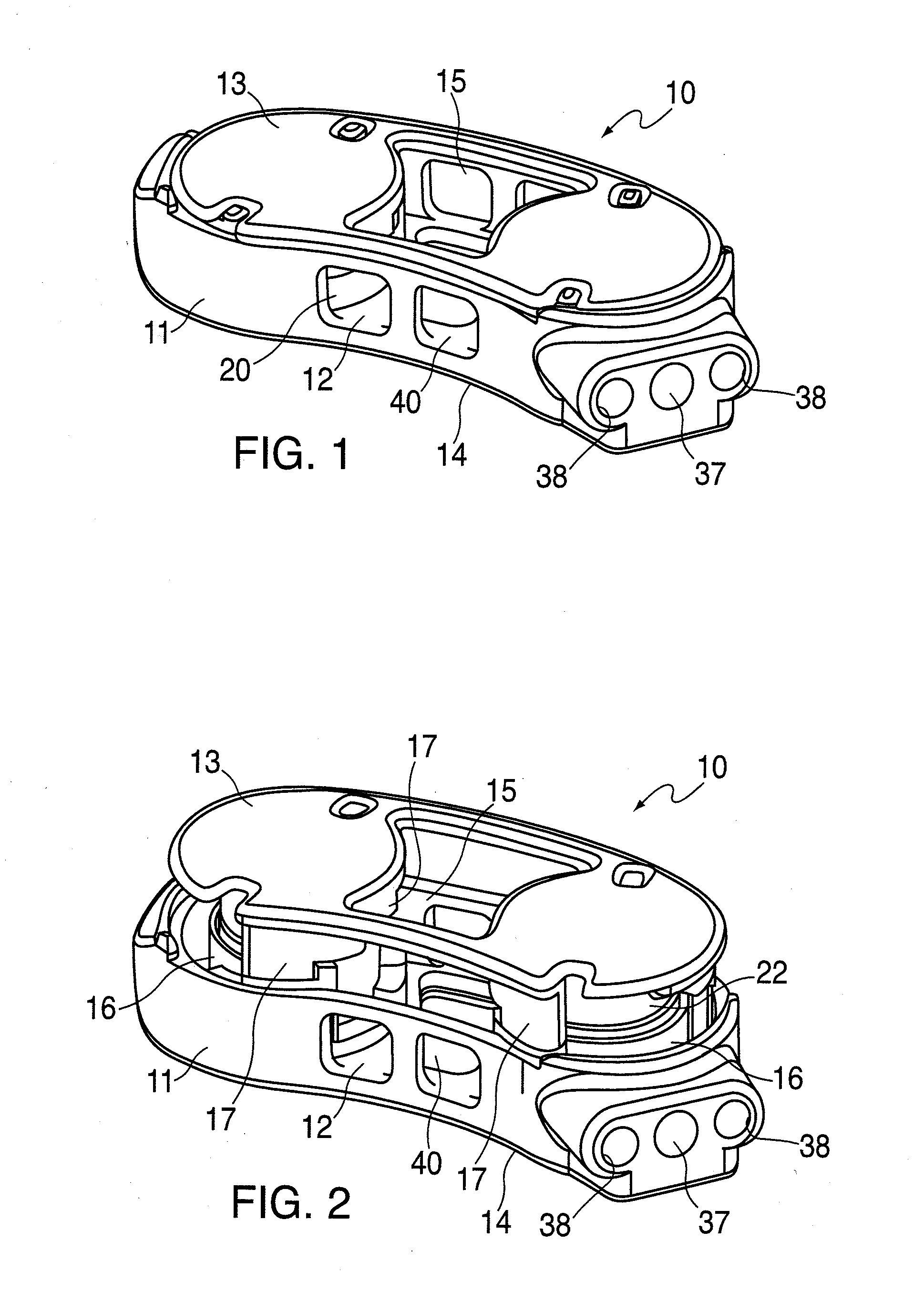
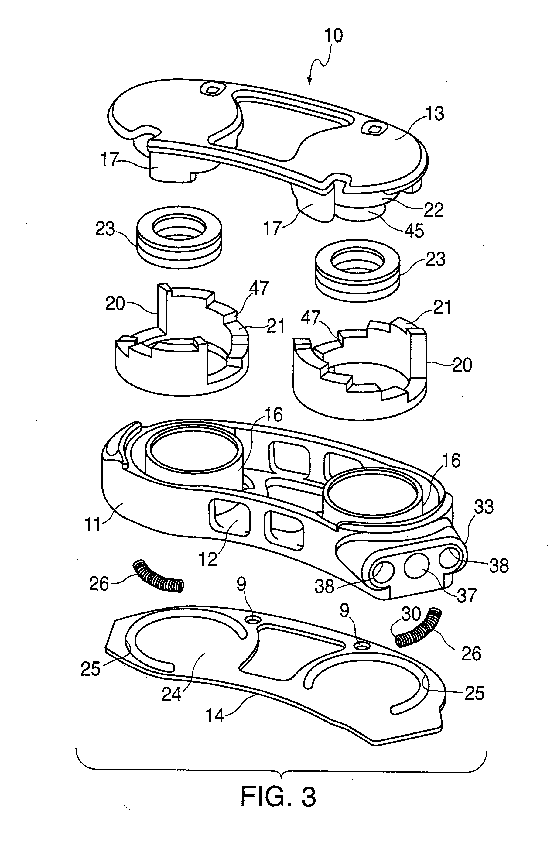
[0072]FIGS. 1-10B illustrate an example of an intervertebral implant 10, a Selectively Expandable Cage (SEC), having features of the invention. The implant 10 generally includes a housing 11, a housing base 12, an interlocking top end plate 13, a bottom end plate 14, an interior cavity 15 within the housing 11 and a pair of cylinders 16. The top and bottom end plates are the bone engaging members of the implant, providing surfaces for engaging vertebrae above and below the implant when placed in the patient. Upper lock supports 17 are attached to the underside of the top end plate 13 thus forming fixed lock members and have multi-stepped lower support surfaces 18 much like an inverted staircase. Lower lock supports 20, having multi-stepped upper support surfaces 21 surround cylinders 16 much like an upright staircase. The multi-stepped support surfaces form the locking surfaces of the lock supports. Pistons 22 are secured to the under surface of top end plate 13. Seal members 23 are...


PUM

PropertyMeasurementUnit
diameteraaaaaaaaaa
diameteraaaaaaaaaa
of rotationaaaaaaaaaa

Abstract

A spinal implant which is configured to be deployed between adjacent vertebral bodies. The implant has at least one extendable support element with a refracted configuration to facilitate deployment of the implant and an extended configuration so as to expand the implant and effectively distract the disc space, stabilize the motion segments and eliminate pathologic spine motion. The implant has a minimal dimension in its unexpanded state that is smaller than the dimensions of the neuroforamen through which it typically passes to be deployed within the intervertebral space. The implant is provided with a locking system having a plurality of linked locking elements that work in unison to lock the implant in an extended configuration. Bone engaging anchors also may be provided to ensure secure positioning

Description

RELATED APPLICATION DATA[0001]This application is a continuation-in-part of International Application No. PCT / US2009 / 67446, designating the United States, filed Dec. 10, 2009, entitled “Lockable Expanding Spine Cage,” and U.S. Nonprovisional Patent Application Ser. No. 12 / 380,840, filed on Mar. 4, 2009, entitled “Lockable Spinal Implant,” which is a nonprovisional of U.S. Provisional Patent Application Ser. No. 61 / 201,518, filed on Dec. 10, 2008, entitled “Lockable Spinal Implant.”[0002]This application is also related to U.S. patent application Ser. No. 11 / 692,800, filed Mar. 28, 2007, entitled “Selectively Expanding Spine Cage, Hydraulically Controllable in Three Dimensions for Vertebral Body Replacement,” which is a continuation-in-part of U.S. Nonprovisional Patent Application Ser. No. 11 / 535,432, filed Sep. 26, 2006, entitled “Selectively Expanding Spine Cage, Hydraulically Controllable in Three Dimensions for Enhanced Spinal Infusion,” which is a nonprovisional of U.S. Provisi...

Claims


Application Information

Patent Timeline
Patent Type & Authority Applications(United States)
IPC IPC(8): A61F2/44
CPCA61F2/30742A61F2310/00023A61F2/442A61F2/4455A61F2/4611A61F2002/30079A61F2002/3008A61F2002/30133A61F2002/30365A61F2002/30405A61F2002/30476A61F2002/30484A61F2002/30499A61F2002/30505A61F2002/30514A61F2002/30522A61F2002/30525A61F2002/3055A61F2002/30551A61F2002/30565A61F2002/30579A61F2002/30581A61F2002/30589A61F2002/30601A61F2002/30841A61F2002/482A61F2002/485A61F2210/009A61F2220/0025A61F2220/0033A61F2230/0015A61F2250/0007A61F2250/0069A61F2250/0098A61F2310/00017A61F2/441A61F2002/30495A61F2/482A61F2/484
Inventor ASHLEY, JOHN E.SIMPSON, PHILIP J.GILLESPIE, WALTER DEANSHULOCK, DAMIEN J.KADABA, MURALIMATSUURA, DAVID G.MANSFIELD, III, GEORGE A.GROTZ, THOMASPRETTI, RUDY
Owner HOWMEDICA OSTEONICS CORP
Why Eureka
Try Eureka