
Stent vascular intervention device and methods for treating aneurysms

a technology of vascular intervention and aneurysm, which is applied in the field of stents, can solve the problems of not being able to deploy a single stent in front, not being able to keep a coil mass in place, and not being able to deploy a single stent, etc., and achieves the effects of reducing the duration, reducing the risk of stent failure, and simple and accurate deploymen

Inactive Publication Date: 2007-01-25
THE RES FOUND OF STATE UNIV OF NEW YORK
View PDF21 Cites 256 Cited by
  • Summary
  • Abstract
  • Description
  • Claims
  • Application Information

AI Technical Summary

Benefits of technology

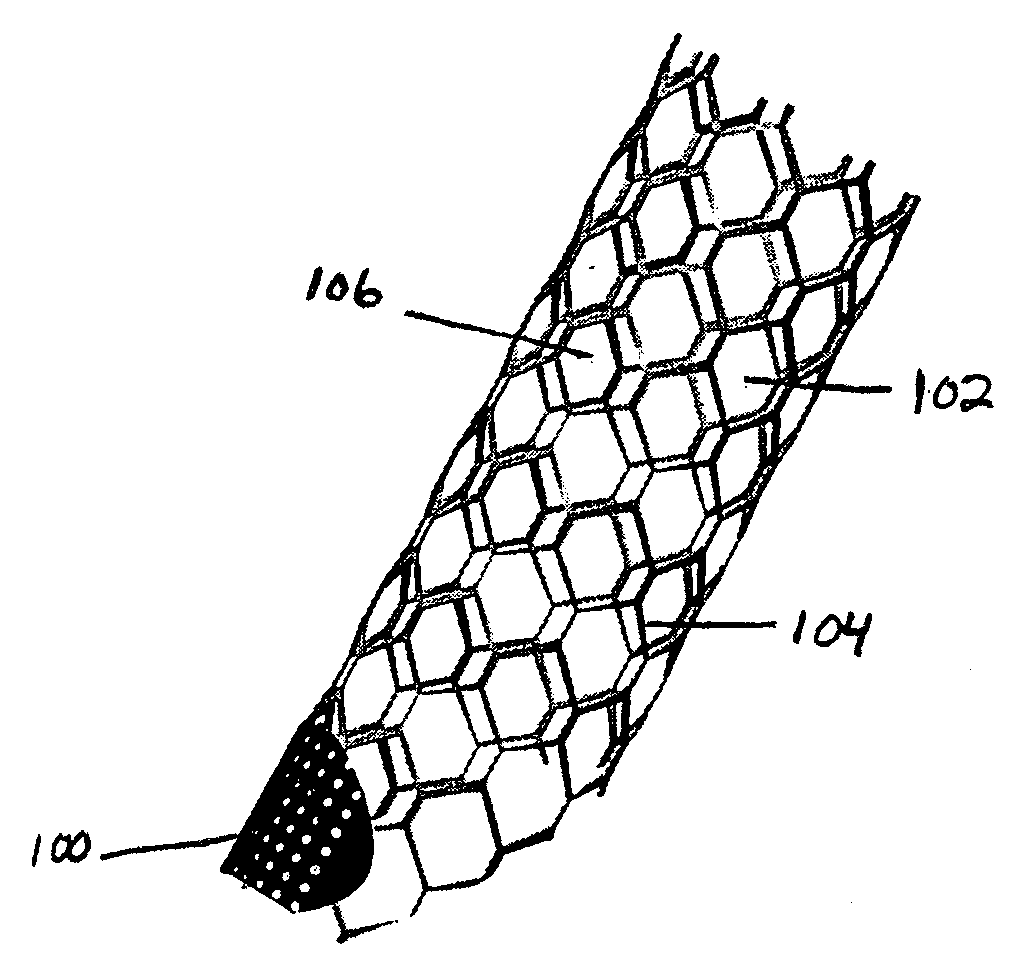
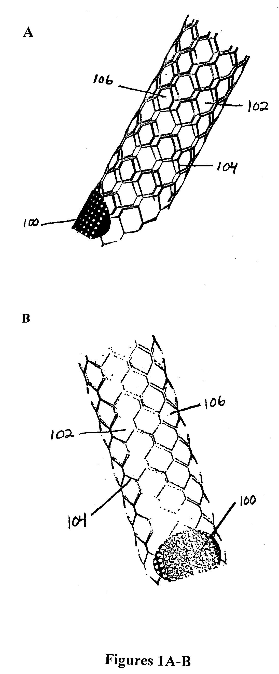
[0016] The stent of the present invention is advantageous in that it enables somewhat straightforward treatment of difficult to treat aneurysms that are inherently non-uniform and non-symmetric in nature. For difficult cases of aneurysms, such as bifurcation or trifurcation aneurysms or where the aneurysm may be wide and not suitable to being treated by any of the existing methods, the stent of the present invention could be used to retard or eliminate flow into the aneurysm without risking filling the aneurysm and causing possible rupture. Even the treatment of basilar tip aneurysms with narrow necks by multiple coil insertion could be shortened in duration by the simple accurate deployment of the stent of the present invention. In the case of a wide neck basilar tip or any other bifurcation aneurysm, it is not possible to keep a coil mass in place nor is it possible to deploy a single stent in front of the aneurysm opening. Especially, for a basilar artery tip where the basilar artery leads into the two posterior cerebral arteries at almost a 90 degree angle, there is no way to deploy a stent to cross between the two posterior communicating cerebral arteries such that the body of the stent lies in front of the aneurysm opening. If two of the asymmetric stents according to the present invention are used, they can be deployed into the two posterior communicating cerebral arteries so that the low porosity patches at the proximal end of the stents meet to retard blood flow into the aneurysm while the stents would be anchored further up along each of the posterior communicating cerebral arteries. Similarly for other aneurysms at other vessel bifurcations, one or more asymmetric stents according to the present invention could be deployed relatively easily yet with great effect on aneurysmal blood flow.

Problems solved by technology

In the case of a wide neck basilar tip or any other bifurcation aneurysm, it is not possible to keep a coil mass in place nor is it possible to deploy a single stent in front of the aneurysm opening.
Especially, for a basilar artery tip where the basilar artery leads into the two posterior cerebral arteries at almost a 90 degree angle, there is no way to deploy a stent to cross between the two posterior communicating cerebral arteries such that the body of the stent lies in front of the aneurysm opening.

Method used


Image

  • Stent vascular intervention device and methods for treating aneurysms
  • Stent vascular intervention device and methods for treating aneurysms
  • Stent vascular intervention device and methods for treating aneurysms

Examples


example 1

Evaluation of an Asymmetric Stent Patch Design

[0056] Aneurysm hemodynamics is known to be significantly affected by the arterial and the aneurysmal wall boundaries which vary from patient to patient (Rhee et al., “Changes of Flow Characteristics by Stenting in Aneurysm Models: Influence of Aneurysm Geometry and Stent Porosity,”Ann. Biomed. Eng., 30:894-904 (2002), which is hereby incorporated by reference in its entirety). Therefore, it is important to consider the specific geometrical characteristics of an artery and an aneurysm to make hemodynamically favorable modifications using placement of a stent.

[0057] An asymmetric stent patch was designed for an anterior cerebral artery aneurysm of a specific patient, where the patch porosity varied across the neck. The local porosity of the patch at the proximal neck was designed to block the strong inflow jet in the patient-specific aneurysm. The purpose of the study was to evaluate the hemodynamic effects of the patient-specific asymm...

example 2

Patient-Specific Aneurysm and Stent

[0059] A 52-year old female patient's ACA aneurysm was selected (FIG. 9). The anatomical geometry was reconstructed from CTA images for flow analysis. Bone structures were removed from vascular anatomy. The bone-removed aneurysm geometry was segmented and smoothed for rendering. Ujiie et al. found that saccular aneurysms were more likely to rupture when the aspect ratios (AR) of the aneurysms were greater than 1.6 (Ujiie et al., “Hemodynamic Study of the Anterior Communicating Artery,”Stroke, 27:2086-2094 (1996); Ujiie et al., “Effects of Size and Shape (Aspect Ratio) on the Hemodynamics of Saccular Aneurysms: A Possible Index for Surgical Treatment of Intracranial Aneurysms,”Neurosurgery, 45(1):119-130 (1999), which are hereby incorporated by reference in their entirety). From the geometric analysis of the reconstructed aneurysm, the aspect ratio of this superior oriented ACA aneurysm was about 2.3; hence, it would be in danger of rupture. Thus, ...

example 3

CFD Simulation

[0061] The untreated and stented aneurysm geometries were meshed with 0.6 and 1.2 million tetrahedral volume elements, respectively. The blood flow was calculated by a finite volume based CFD code, StarCD® (CD-adapco, Melville, N.Y.) under the assumption of incompressible flow. The calculation was performed with both steady and pulsatile flow conditions (FIG. 10). In addition to solving the governing equations of the flow, the scalar transport equations, which is similar to the Navier-Stokes equations but describe the motion in a scalar, were added for the virtual angiographic visualization. Therefore, sequential operations to solve the scalar transport equations were performed during each iteration. The second order accuracy was obtained by choosing a central differencing scheme for solving both flow and scalar equations. In this study, the average Reynolds number (Re) of the flow was 678, which is higher than normal but still in the range of typical flows known to o...


PUM


Abstract

The present invention relates to a stent including a variable porosity, tubular structure having pores defined by structural surfaces. The tubular structure has a low porosity region in proximity to or at either end of the tubular structure, where the low porosity region is less porous than other regions located on the tubular structure and fully or partially obstructs passage of fluid. Any arcuate path that starts at one point within the low porosity region and goes around the perimeter of the tubular structure to stop at the same point within the low porosity region must have at least a portion that is outside of the low porosity region. Also disclosed is a method of modifying blood flow within and near an opening of an aneurysm in a blood vessel by deploying one or more stents of the present invention near an opening of the aneurysm in a blood vessel.

Description

[0001] This application claims the benefit of U.S. Provisional Patent Application Ser. No. 60 / 701,271, filed Jul. 21, 2005, which is hereby incorporated by reference in its entirety.[0002] This work was in part supported by the National Institutes of Health (Grant Nos. R01 EB002873 and R01 NS43024). The U.S. Government may have certain rights in this invention.FIELD OF THE INVENTION [0003] The present invention relates to medical devices, stents in particular, and methods of treating cerebrovascular aneurysms using endovascular deployment of such stents. BACKGROUND OF THE INVENTION [0004] After heart disease and cancer, stroke is the leading cause of death and adult disability in the United States. After stenoses due to plaque or thrombosis, aneurysms and their rupture is the leading cause of stroke. An intracranial aneurysm is a bulge in an artery of the brain that is prone to rupture. A ruptured intracranial aneurysm may lead to subarachnoid hemorrhage (SAH) with a high mortality ...

Claims


Application Information

Patent Timeline
Patent Type & Authority Applications(United States)
IPC IPC(8): A61F2/06A61F2/82A61F2/86A61F2/90
CPCA61F2/86A61F2/90A61F2250/0023A61F2002/823A61F2002/067
Inventor RUDIN, STEPHEN
Owner THE RES FOUND OF STATE UNIV OF NEW YORK
Learn More