Directable nozzle for rock drilling bits

a drilling bit and direct-type technology, applied in the field of drilling bits, can solve the problems of reducing the penetration rate, redrilling cuttings, and applying a high compressive load to the rock by the teeth or carbide insert, so as to and prevent excessive nozzle angularity. resulting in inefficient hydraulic performance of the drill bit

Inactive Publication Date: 2006-11-30
GEN ELECTRIC CAPITAL +2
View PDF35 Cites 28 Cited by
  • Summary
  • Abstract
  • Description
  • Claims
  • Application Information

AI Technical Summary

Benefits of technology

The present invention relates to a new type of nozzle system for use in oil drilling operations. One important aspect of this innovation is its unique directedness, which means that even if people have little training or experience, they can complete tasks related to the nozzle without facing common issues such as poor directionality. This reduces risks like internal turbuline, hydraulic erosion, premature failures of equipment, and other complications. Additionally, the nozzle system is affordable, easy to assemble, and reusable. It includes a sphere-shaped nozzle with an extended part called the extension, along with a removable retainer that helps align the nozzle's components properly. Overall, these technical improvements make the process of installing and maintaining the nozzle system much simpler and safer.

Problems solved by technology

The technical problem addressed in this patent text is the need for a directly controllable nozzle design for drill bits in oil and gas exploration that is affordable, easy to install, reusable, and properly aligns to improve hydraulic performance without causing damage to equipment or premature failures due to unstable alignment. Existing solutions tend to be too complicated and expensive to make and assemble, leading to increased labor and training requirements.

Method used


Image

  • Directable nozzle for rock drilling bits
  • Directable nozzle for rock drilling bits
  • Directable nozzle for rock drilling bits

Examples


Embodiment Construction

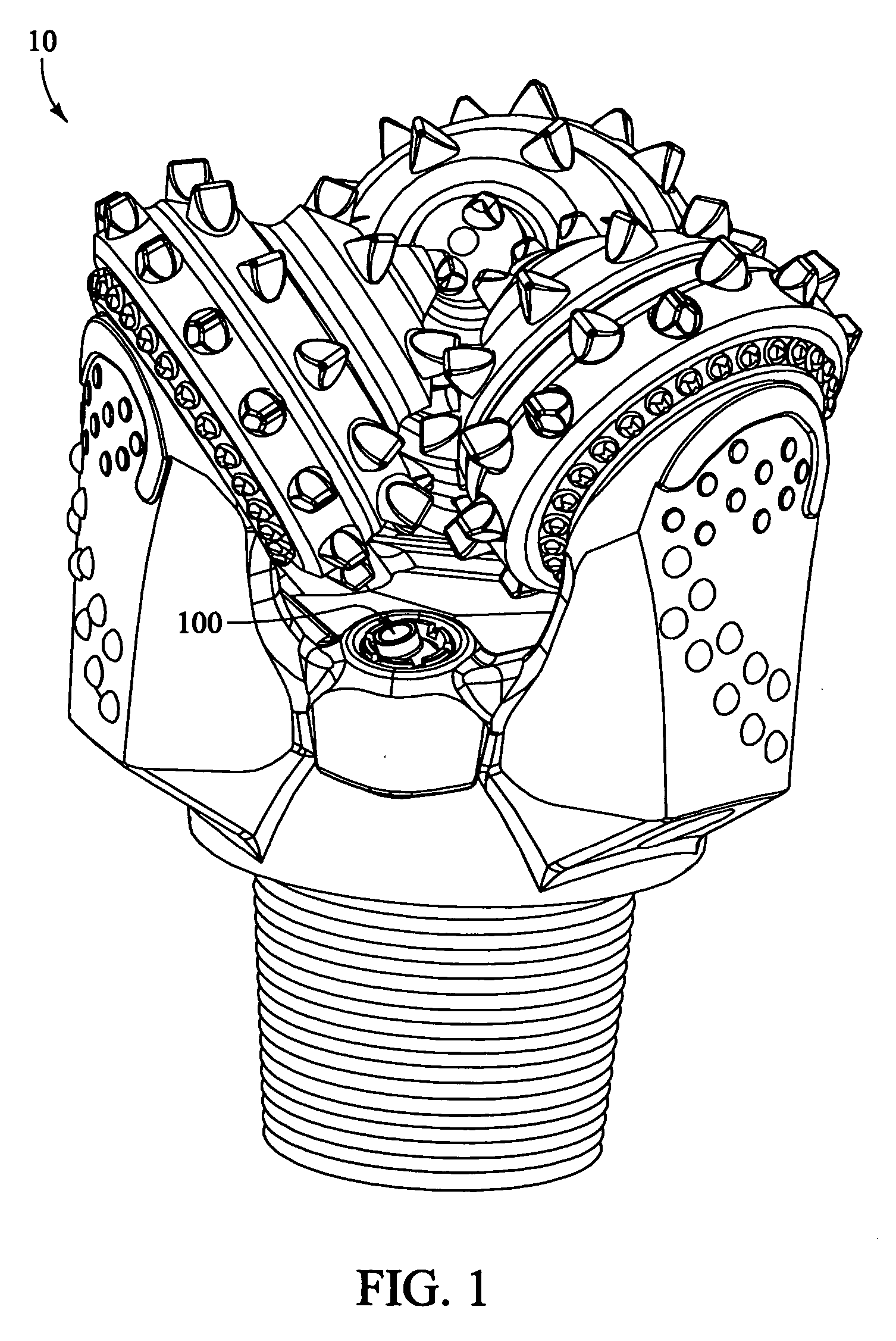
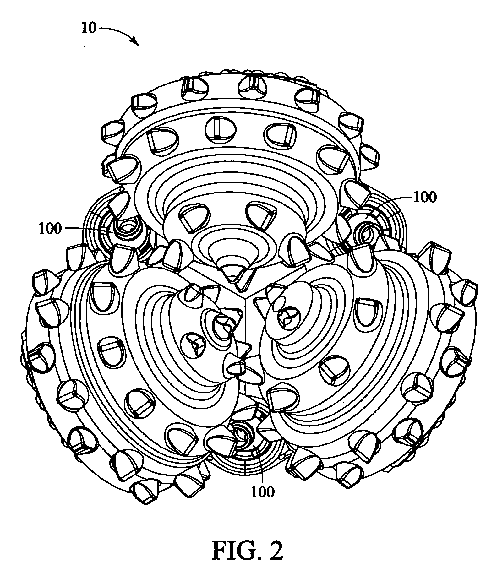
[0039]FIG. 1 is an isometric view of a rotary drill bit 10 having a directable nozzle assembly 100 installed in accordance with a preferred embodiment of the present invention. FIG. 2 is a top view of rotary drill bit 10 of FIG. 1, illustrating multiple directable nozzle assemblies 100 installed in accordance with a preferred embodiment of the present invention.

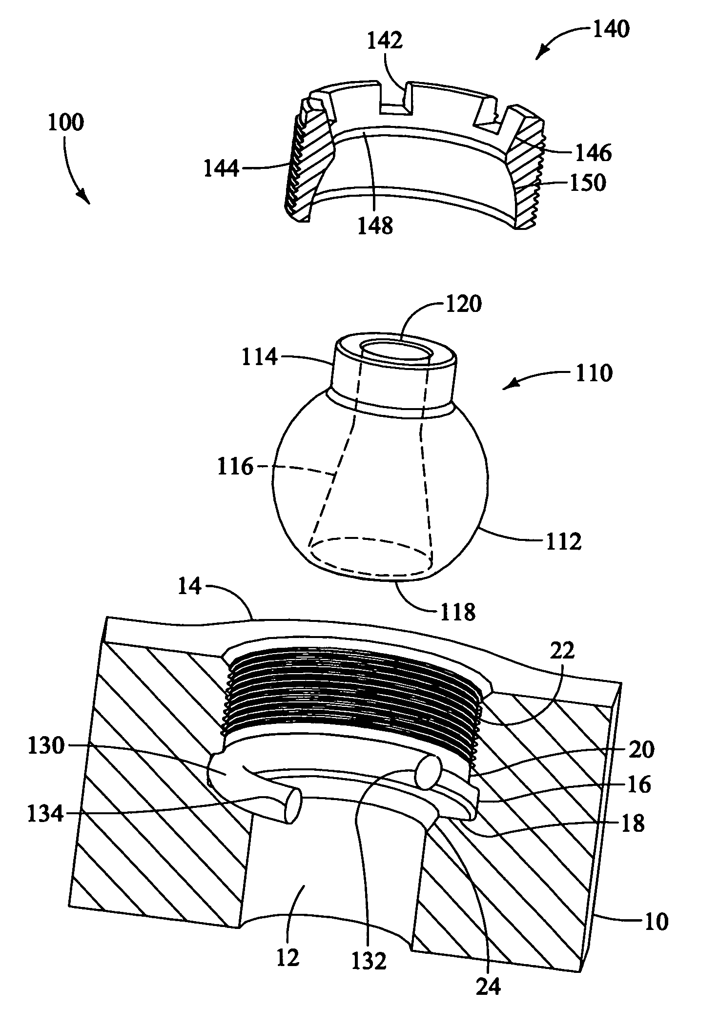
[0040]FIG. 3 is a side-sectional view of a known art interchangeable nozzle assembly 200 installed in a nozzle boss 14 of rotary drill bit 10. In the view, it is seen that a nozzle 210 is non-directable. Nozzle 210 is secured in fixed alignment with a flow port 12 in rotary drill bit 10. A seal 130 is located in a groove 16 to prevent drilling fluid from bypassing nozzle 210. Drilling fluid passes through flow port 12 of rotary drill bit 10 and then through a nozzle passage 216 of nozzle 210. The drilling fluid enters a first portal 218 and exits a second portal 220, which is significantly smaller in diameter than first port...


PUM


Abstract

A directable nozzle assembly 100 for a rotary drill bit 10 is disclosed, having a nozzle 110 comprising a generally spherical body 112, and having an extension 114 extending from the body 112. A passage 116 extends through the body 112 and extension 114 portions. A seal 130 is provided for sealing the nozzle 110 to the nozzle boss area 14 of the rotary drill bit 10. A removable retainer 140 is provided having a hollow interior, an angle limiter surface 146, and an interior compression surface 150. In another embodiment is a wear resistant sleeve 160, having a collar 162 with a nozzle seat 164 and a body 170, inserted into a flow port 12 of rotary drill bit 10.

Description


Claims


Application Information

Patent Timeline
Owner GEN ELECTRIC CAPITAL
Why Eureka
Try Eureka