Magnet embedded motor, rotor unit, and method for manufacturing rotor unit
a technology of embedded motors and rotor units, which is applied in the direction of mechanical energy handling, magnetic circuit shapes/forms/construction, cooling/ventilation arrangements, etc., can solve the problems of affecting the retention of the manufacturing cost of the magnet embedded motor and the rotor unit of the motor, the assembling process may occasionally be complicated, and the motor may require a lo
- Summary
- Abstract
- Description
- Claims
- Application Information
AI Technical Summary
Problems solved by technology
Method used
Image

Examples
first embodiment
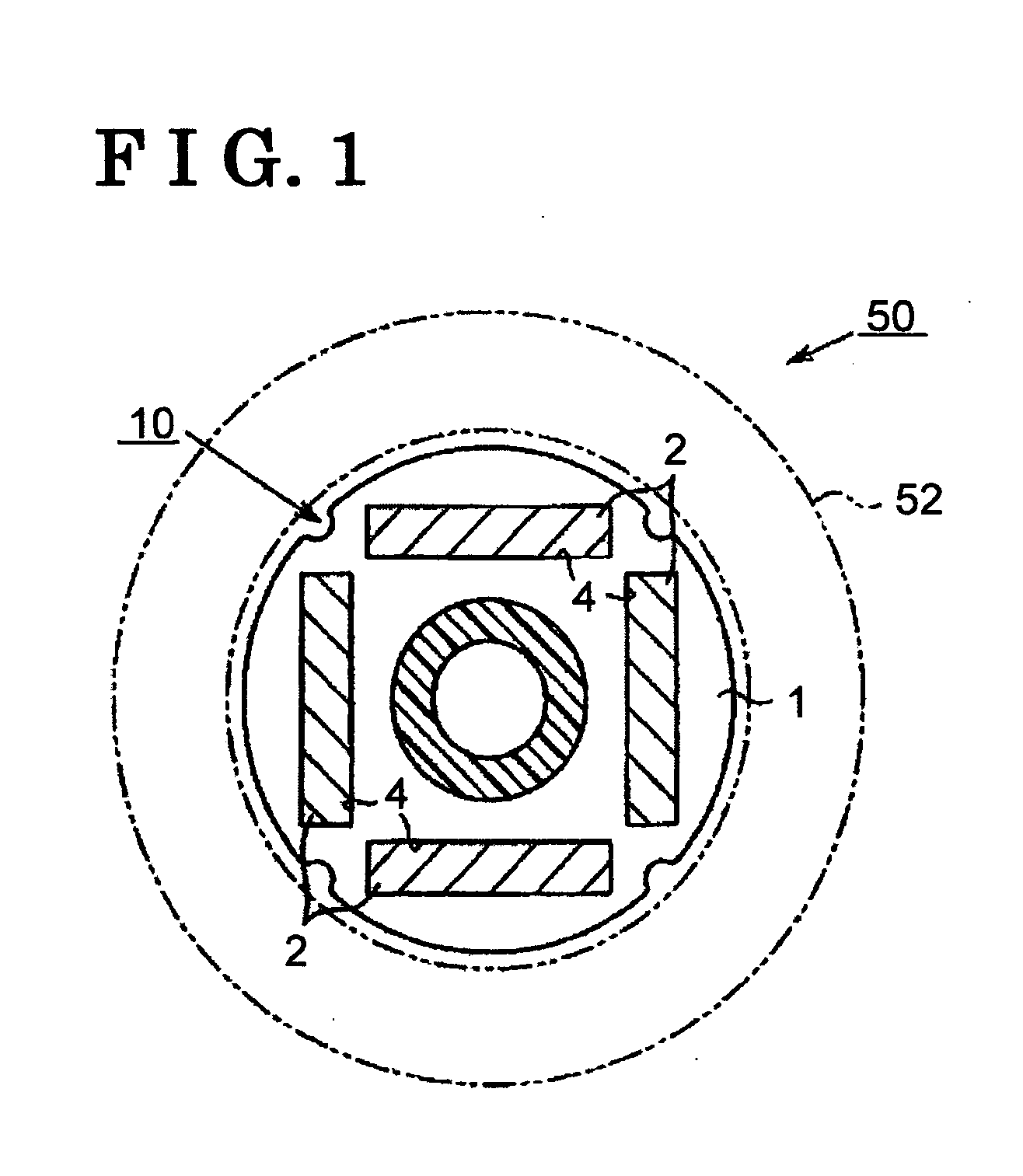
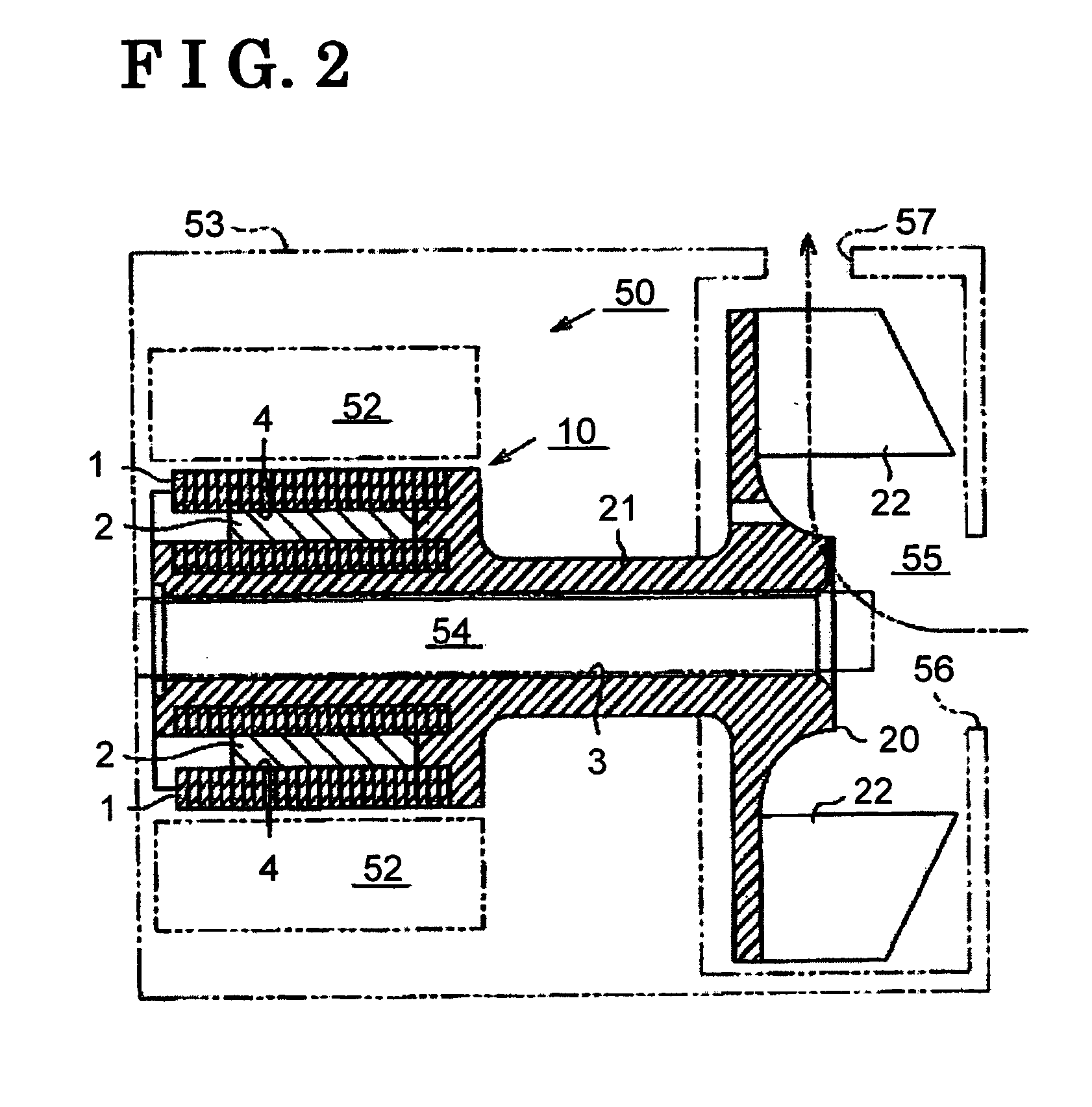
[0022] the present invention will be explained hereinafter. An interior permanent magnet motor applied to a pump apparatus (i.e., a water pump) will be explained hereinafter. With reference to FIG. 1, the motor 50 (i.e., au interior permanent magnet motor) includes a rotor 10 having plural magnets 2 which are embedded therein. The rotor 10 is provided with, at an outer side thereof, a stator 52 having a three phase (U, V, W) motor coil (not shown). A rotating magnetic field is formed and the rotor 10 upon an energization of a motor coil. Further, the rotor 10 is rotated based on a relation between magnetic field flux of the magnet 2 and the rotating magnetic field.
[0023] As illustrated in FIG. 2, the rotor 10 includes a yoke 1 at which a magnetic pass of the magnet 2 is formed. The yoke 1 is formed with second holes 4 into which each magnet 2 is inserted. According to the first embodiment of the present invention, the yoke 1 is formed by laminating magnetic steel plates. Further, ac...
second embodiment
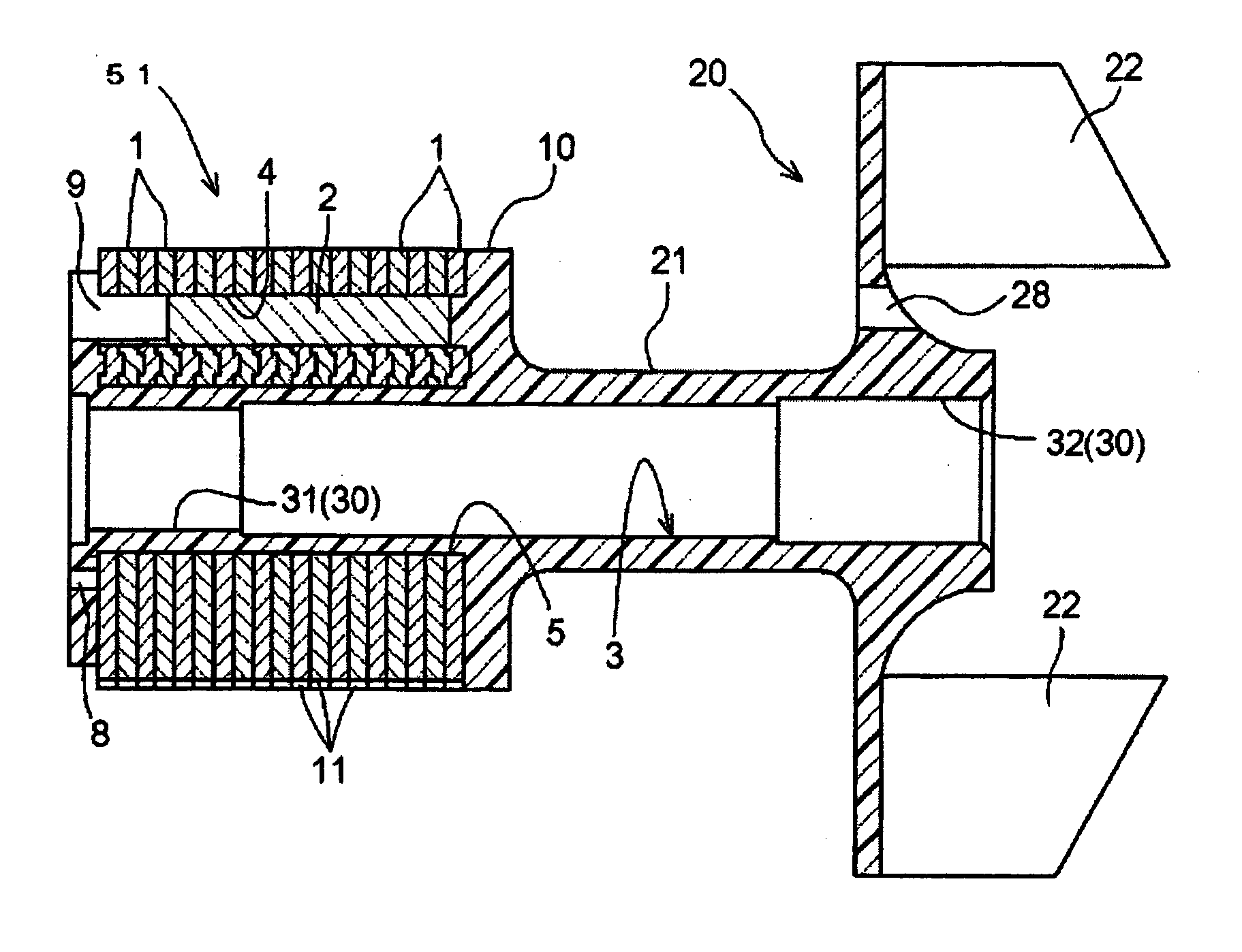
[0031] with reference to FIGS. 4-5, a pad of the list hole 3 to which the bearing 31 is provided is formed by applying the resin material at an inside thereof. The bearing 31, which is slidable with the rotation shaft 54, and the first hole 3 of the yoke 1 are required to be fixed with each other. Mote particularly, a relative rotation between the bearing 31 and the first hole 3 of the yoke 1 caused by a rotational force transmitted from the rotation shaft 54 is necessarily prevented. According to the present invention, each vertex of the octagon of the first hole 3 serves as a stopper and the relative rotation between the yoke 1 and the bearing 31 is thereby prevented. Therefore, a stopper mechanism such as an opening or a protrusion is not required unlike the rotor unit disclosed in JP2004-48827.
[0032] A part of the first hole 3 to which the bearings 30 are provided is formed with a stepped portion to correspond with a rotation shaft (not shown) which is formed into a taper shape ...
PUM
 Abstract
Description
Claims
Application Information
 - R&D Engineer
- R&D Manager
- IP Professional
- Industry Leading Data Capabilities
- Powerful AI technology
- Patent DNA Extraction
Browse by: Latest US Patents, China's latest patents, Technical Efficacy Thesaurus, Application Domain, Technology Topic.
© 2024 PatSnap. All rights reserved.Legal|Privacy policy|Modern Slavery Act Transparency Statement|Sitemap