
Image processing to reduce blocking artifacts

a technology of image processing and artifacts, applied in the field of image processing, can solve the problems of additional information, information must be transferred, visible edges at the block boundary, etc., and achieve the effect of reducing blocking artifacts

Inactive Publication Date: 2006-12-07
TRIDENT MICROSYSTEMS (FAR EAST) LTD
View PDF6 Cites 118 Cited by
  • Summary
  • Abstract
  • Description
  • Claims
  • Application Information

AI Technical Summary

Benefits of technology

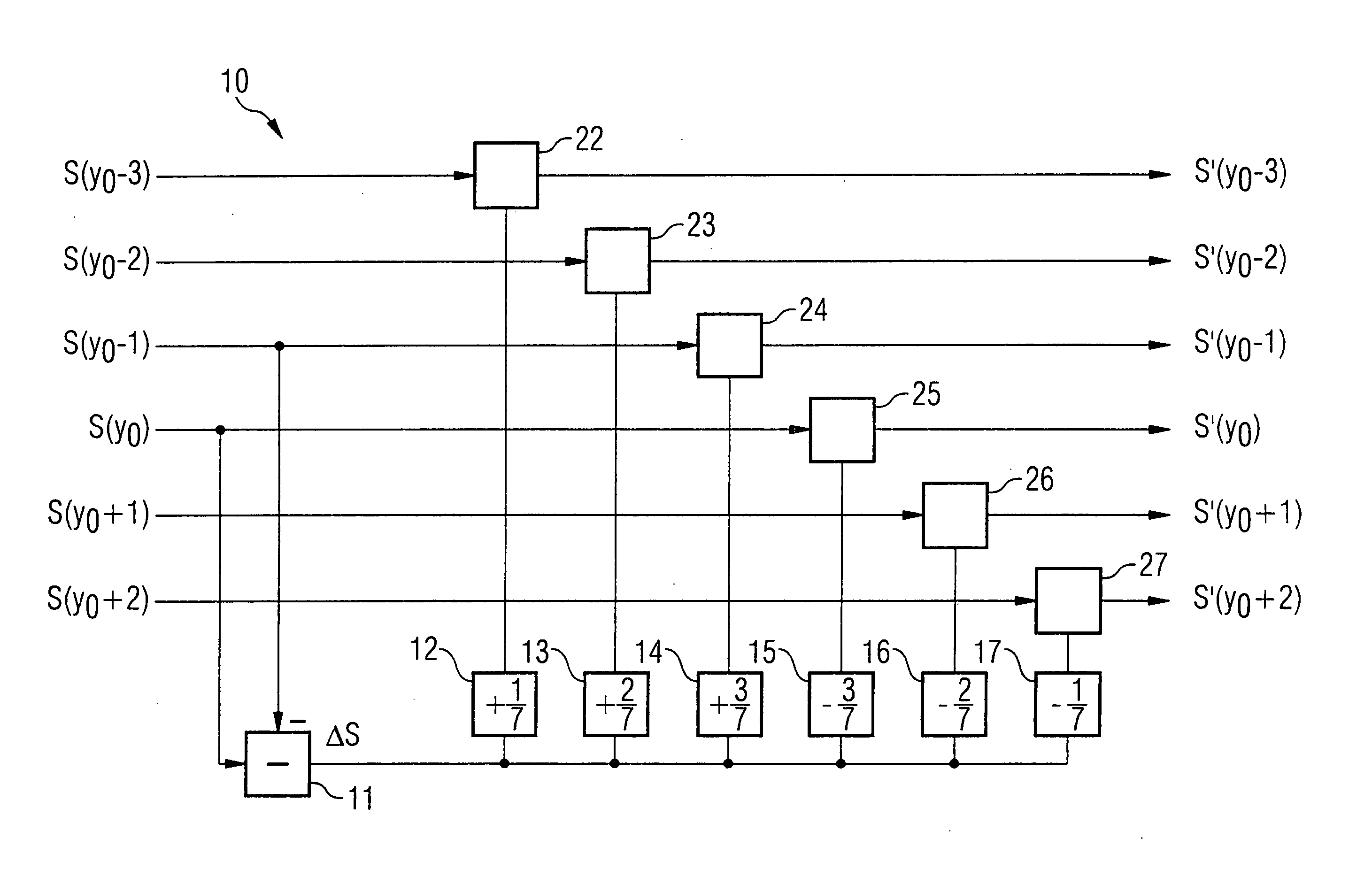
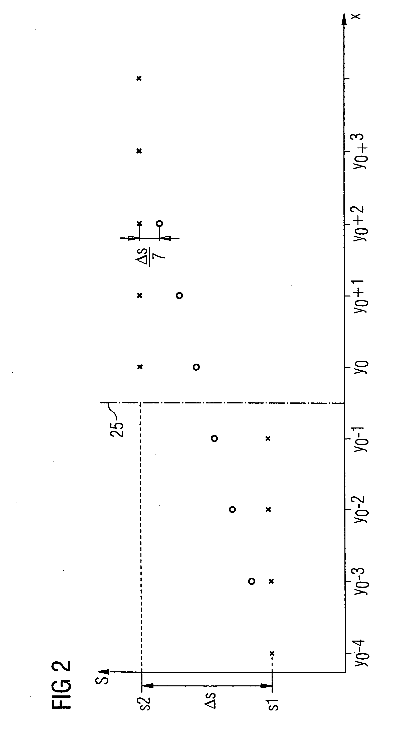
[0015] Processing to reduce blocking artifacts in an image comprising a first image block and a second image block separated by a block boundary, includes, generating a main gradient value which is a function of a first pixel difference between a first pixel located in the first image block a second pixel located in the second image block, where the first and second pixel are located adjacent to each other on a first axis running vertically relative to the block boundary. In addition, at least one secondary gradient value is generated which is a function of a second pixel difference between at least two pixels located adjacent to each other in the first image block on the first axis, and a function of a third pixel difference between at least two pixels located adjacent to each other in the second image block on the first axis. The first and second image blocks are filtered, at least in the region of a block boundary between the first and second image blocks as a function of a ratio between the main gradient value and the at least one secondary gradient value.
[0016] The ratio between the main gradient value and the secondary gradient value provides information about the presence of blocking artifacts in the region of the block boundary between the first and second image blocks. When the ratio of the main gradient value to the secondary gradient value indicates the presence of a blocking artifact, filtering of the first and second image blocks is effected, at least in the region of the block boundary, with the goal of reducing blocking artifacts.

Problems solved by technology

The quantization of the individual image blocks is necessarily associated with a loss of information that can result in visible edges at the block boundaries during the reconstruction.
A problem with the two above-described methods is that additional information aside from the image information must be transferred or be present to reduce the blocking artifacts.
One method that does not require this additional information is described, for example, in “Reduction of Blocking Artifact Images Using Wavelet Transform”, IEEE Transactions on Circuits and Systems for Videotechnology, Vol. 8, No. 8,June 1998.This method is based on a two-stage wavelet transform and thus involves a not-inconsiderable implementation complexity.

Method used


Image

  • Image processing to reduce blocking artifacts
  • Image processing to reduce blocking artifacts
  • Image processing to reduce blocking artifacts

Examples


Embodiment Construction

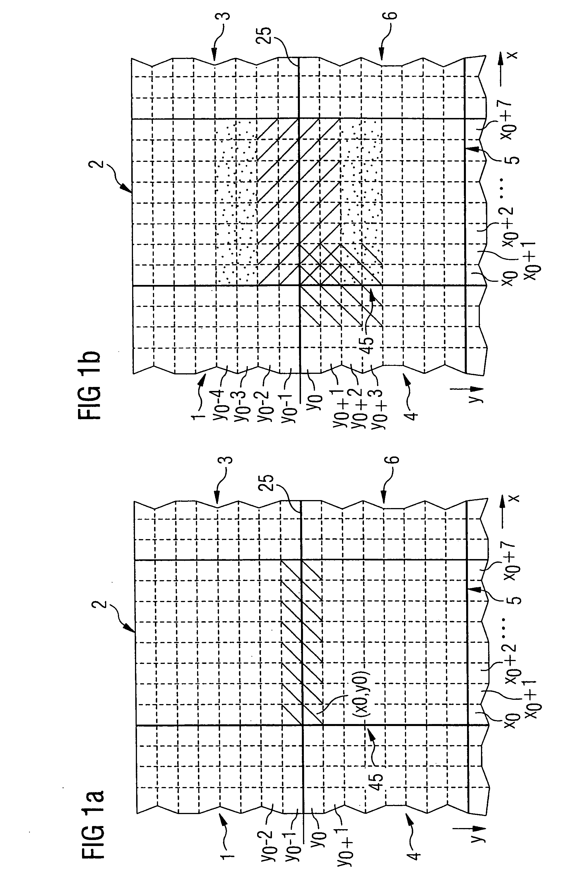
[0025]FIGS. 1A and 1B pictorially illustrate a section of an image subdivided into multiple image blocks. Each of the individual image blocks has a number of adjacent pixels, for example a matrix of 8×8 pixels. The individual pixels are associated with specific image information values.

[0026] The image is, for example, reconstructed from an image data stream transferring quantized image information. Due to the quantization of the image information values before the data transfer, an inevitable loss of information occurs that can manifest itself in the reconstructed image as blocking artifacts at the block boundaries between adjacent image blocks. A blocking artifact of this type displays, for example, a visible line in the image along the block boundary between the two blocks.

[0027] The following discussion examines the vertically adjacent first and second image blocks 2, 5, between which runs a block boundary 25. A vertical axis of the image section is designated as the y-axis, w...


PUM


Abstract

Processing to reduce blocking artifacts in an image comprising a first image block and a second image block separated by a block boundary, includes, generating a main gradient value which is a function of a first pixel difference between a first pixel located in the first image block a second pixel located in the second image block, where the first and second pixel are located adjacent to each other on a first axis running vertically relative to the block boundary. In addition, at least one secondary gradient value is generated which is a function of a second pixel difference between at least two pixels located adjacent to each other in the first image block on the first axis, and a function of a third pixel difference between at least two pixels located adjacent to each other in the second image block on the first axis. The first and second image blocks are filtered, at least in the region of a block boundary between the first and second image blocks as a function of a ratio between the main gradient value and the at least one secondary gradient value.

Description

PRIORITY INFORMATION [0001] This patent application claims priority from German patent application 10 2005 025 629.5 filed Jun. 3, 2005,which is hereby incorporated by reference. BACKGROUND OF THE INVENTION [0002] The invention relates to the field of image processing, and in particular to reducing blocking artifacts in images that have been reconstructed from transferred image information. [0003] The transfer of image information may include a spatial to temporal transfer of image information, that is, a storing and retrieval of image information. A known approach to transferring image data is to subdivide the individual images to be transferred into blocks, each one having multiple pixels, and to quantize and encode block-by-block the image information values associated with the individual pixels. A procedure of this type is found, for example, in the MPEG method. The quantization may vary for individual blocks. [0004] When these image data are received, a block-by-block decoding ...

Claims


Application Information

Patent Timeline
Patent Type & Authority Applications(United States)
IPC IPC(8): G06K9/40
CPCH04N19/86
Inventor PIASTOWSKI, PATRICK
Owner TRIDENT MICROSYSTEMS (FAR EAST) LTD
Learn More