Splice protection heater, fusion splicer including the splice protection heater, and fusion splicing method

a technology of fusion splicing and heater, which is applied in the direction of instruments, optical light guides, optics, etc., can solve the problems of inability to perform proper protection process, fusion-spliced portion may be broken or damaged, and loss of time, etc., to achieve efficient thermal protection process, fast and efficient performance, and sufficient heating time

Active Publication Date: 2006-12-14
SUMITOMO ELECTRIC IND LTD
View PDF11 Cites 47 Cited by
  • Summary
  • Abstract
  • Description
  • Claims
  • Application Information

AI Technical Summary

Benefits of technology

[0009] An object of the present invention is to provide a splice protection heater capable of efficiently performing a thermal protection process without causing idle time between splicing operation and the following protection operation, and further capable of performing a thermal protection process suitable for each protection sleeve, a fusion splicer including the splice protection heater, and a fusion splicing method. A further object of the present invention is to provide a splice protection heater capable of quickly and efficiently performing a thermal protection process with just sufficient heating time for the protection operation and capable of preventing human error in the ON / OFF operations of a switch for a heating element, a fusion splicer including the splice protection heater, and a fusion splicing method.

Problems solved by technology

However, a loss of time may be incurred, for example, if an operator forgets to turn the switch ON after having disposed a fusion-spliced portion in the splice protection heater.
Furthermore, a fusion-spliced portion may be broken or damaged if an operator removes the unprotected optical fiber from the splice protection heater after a fixed time without becoming aware that he has not turned the switch ON.
Moreover, a proper protection process may not be performed because of an insufficient actual heating time if the switch is turned ON before a fusion-spliced portion is disposed in the housing part of the splice protection heater.
An operator may forget to manually switch the heating element ON or OFF regardless of the care taken and an ON / OFF timing of the switch may not be uniform.
This arrangement cannot be applied, therefore, if different types of protection sleeves that require different heating times for processing are used.
In addition, once the switch of the heating element is turned ON, protection sleeves cannot be added until the thermal protection process ends.
Therefore, even though the splicing operation is performed quickly, the thermal protection operation to the following fusion spliced fiber cannot be started and an idle time in a standby state is caused until the protection process of the preceding fusion spliced fiber has been completed.
Although splicing operation can be performed parallel to the protection operation, the fusion-spliced portion as itself that has not yet been protected is extremely weak.
Therefore, a situation where many fusion-spliced optical fibers waiting protection processing are accumulated may cause problems in which a fusion-spliced portion is broken, damaged or the like by an external force.

Method used


Image

  • Splice protection heater, fusion splicer including the splice protection heater, and fusion splicing method
  • Splice protection heater, fusion splicer including the splice protection heater, and fusion splicing method
  • Splice protection heater, fusion splicer including the splice protection heater, and fusion splicing method

Examples


first embodiment

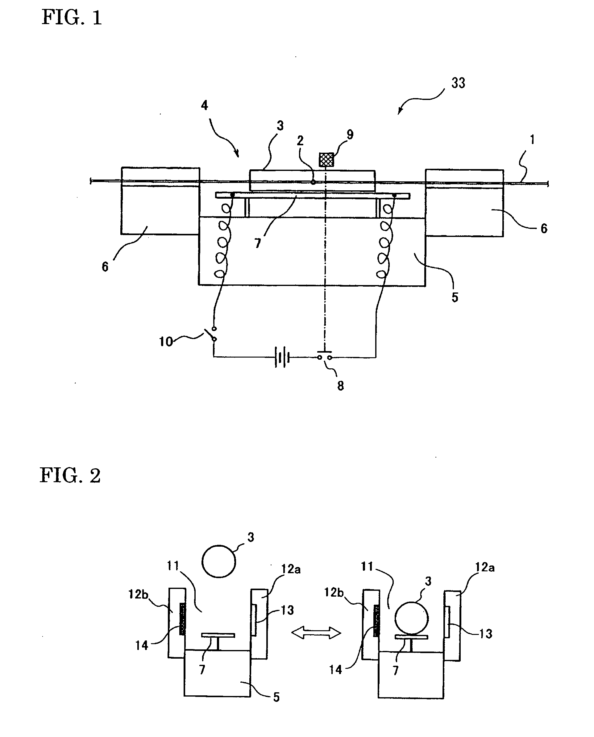
[0033]FIG. 1 is a schematic drawing showing of a splice protection heater according to the present invention. The splice protection heater 33 performs a thermal protection process with a heating part 4 on an optical fiber 1 (single fiber or optical fiber ribbon) at a fusion spliced portion 2 covered with a protection sleeve. The heating part 4 is provided with a pair of clampers 6 disposed at bilateral ends of a base 5, and a heating element 7 that is disposed at a center portion of the heating part. The heating part 4 supports a fusion-spliced optical fiber without slack by the left and right clampers 6.

[0034] After the fusion-spliced portion 2 that is covered with the protection sleeve 3 has been placed on the heating element 7, the heating part 4 is enclosed by a heater cover (not shown in FIG. 1). Then, a switch 8 is turned ON to provide current to the heating element 7 and to heat shrink the protection sleeve 3. When heating process for the protection sleeve 3 ends after heatin...

second embodiment

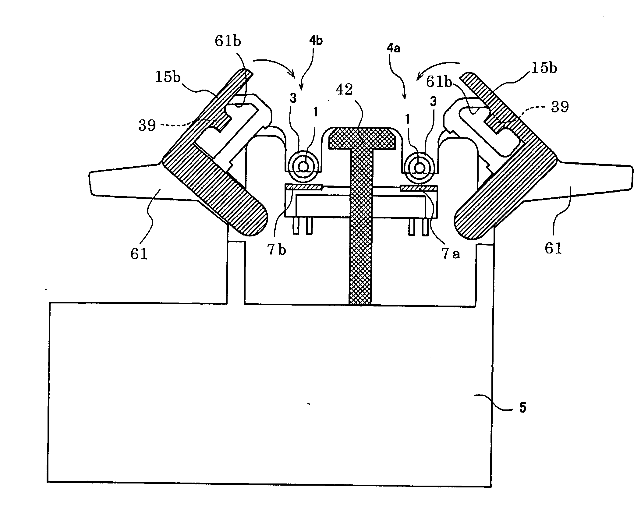
[0052] FIGS. 12˜15 are schematic diagrams illustrating a splice protection heater according to the present invention. FIG. 12 is a perspective view, FIG. 13 is a front view with the heater cover removed, FIG. 14 is a cross sectional view taken along a section line a-a of FIG. 13 with the clamper and heater cover opened, and FIG. 15 is a cross sectional view taken along a section line b-b of FIG. 13 with the clamper and heater cover opened, also. As shown in FIG. 12, the splice protection heater 33b is provided with at least two heating unit 4a and 4b as a heating part 4 on a base 5, such that heating elements 7a and 7b, which can be turned ON and OFF by independent switches, are respectively disposed in each heater 4a and 4b. FIG. 12 shows a state in which the optical fiber 1 and the protection sleeve 3 have not attached to the splice protection heater.

[0053] Each of the heating unit 4a and 4b has a housing part to accommodate the protection sleeve 3, and each of the heating unit 4a...


PUM


Abstract

A splice protection heater capable of quickly and efficiently performing a fusion process without an excessive heating time, a fusion splicer including the splice protection heater, and a fusion splicing method are provided. The apparatus has a heating part for heat shrinking a protection sleeve that covers a fusion spliced portion of an optical fiber, a plurality of heating elements that can individually heat a plurality of protection sleeves with different timings by being individually turned ON/OFF by switches, or a heating element turned ON/OFF by a switch. This apparatus may also be provided with detecting section that detects whether or not the protection sleeve is set on the heating element, and turns the switch ON/OFF.

Description

BACKGROUND OF THE INVENTION [0001] 1. Field of the Invention [0002] The present invention relates to a splice protection heater for protecting a fusion spliced portion of an optical fiber by heat shrinking a protection sleeve covering the fusion spliced portion, a fusion splicer including the splice protection heater, and a fusion splicing method. [0003] 2. Description of the Background Arts [0004] Fusion splicing of optical fibers is performed by heating and fusing abutting end portions of glass fibers that have been exposed by removing protective coatings on splicing ends of the optical fibers. Since a part of the fusion spliced optical fiber where the glass fiber has been exposed is mechanically weak, it is necessary to protect the part with a protection sleeve. The protection sleeve is usually configured by accommodating hot-melt adhesive resin and a tensile body (also referred to as a reinforcing rod) within a heat shrinkable tube that shrinks in the radial direction when heat ...

Claims


Application Information

Patent Timeline
Patent Type & Authority Applications(United States)
IPC IPC(8): G02B6/00
CPCG02B6/2553G02B6/2551G02B6/245G02B6/255
Inventor SATO, RYUICHIROITO, KENSUKEWATANABE, TSUTOMU
Owner SUMITOMO ELECTRIC IND LTD
Why Eureka
Try Eureka