Scannable dynamic circuit latch

a dynamic circuit and latch technology, applied in the field of latches, can solve the problems of insufficient delay in the circuit, scannable latch inserting substantial delay, and rare scannable latches

Active Publication Date: 2007-01-11
INTELLECTUAL VENTURES HOLDING 81 LLC
View PDF89 Cites 3 Cited by
  • Summary
  • Abstract
  • Description
  • Claims
  • Application Information

AI Technical Summary

Problems solved by technology

Such applications rarely include scannable latches for similar reasons, e.g., the inclusion of a scannable latch inserts substantial delay into the circuit.
While scannable latches are desirable, in order to allow for improved logic testing than is otherwise possible, the delay imposed is too significant.

Method used


Image

  • Scannable dynamic circuit latch
  • Scannable dynamic circuit latch
  • Scannable dynamic circuit latch

Examples


Embodiment Construction

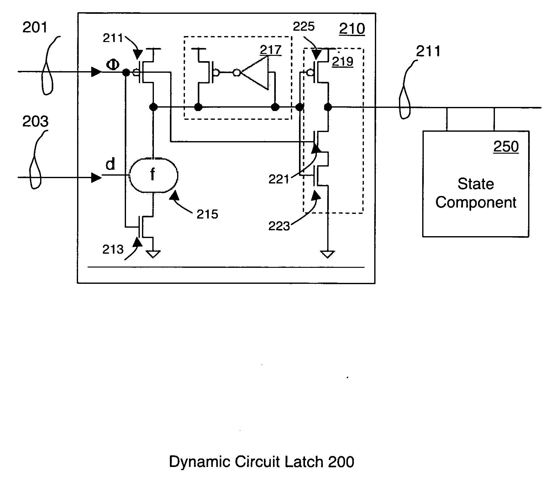
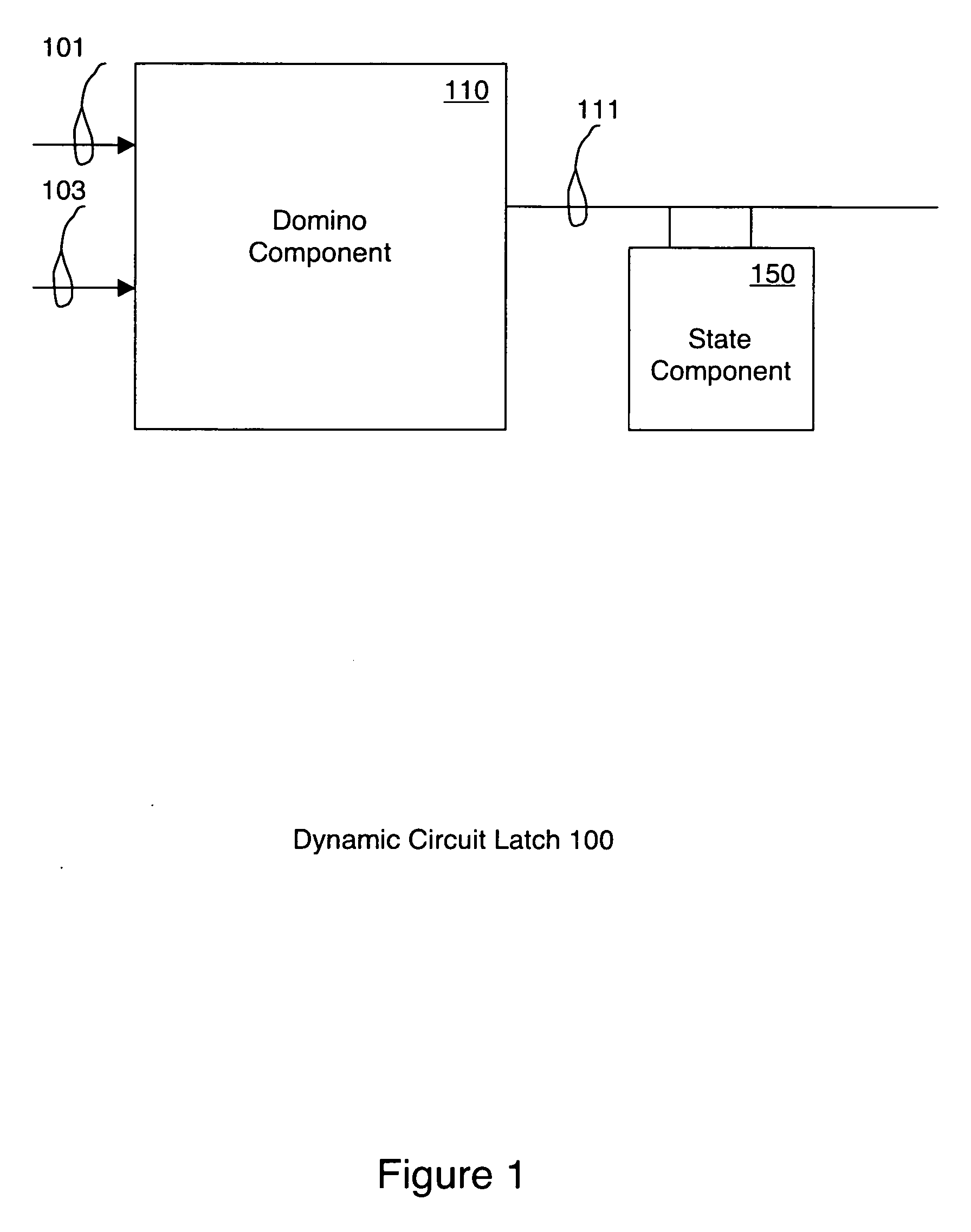
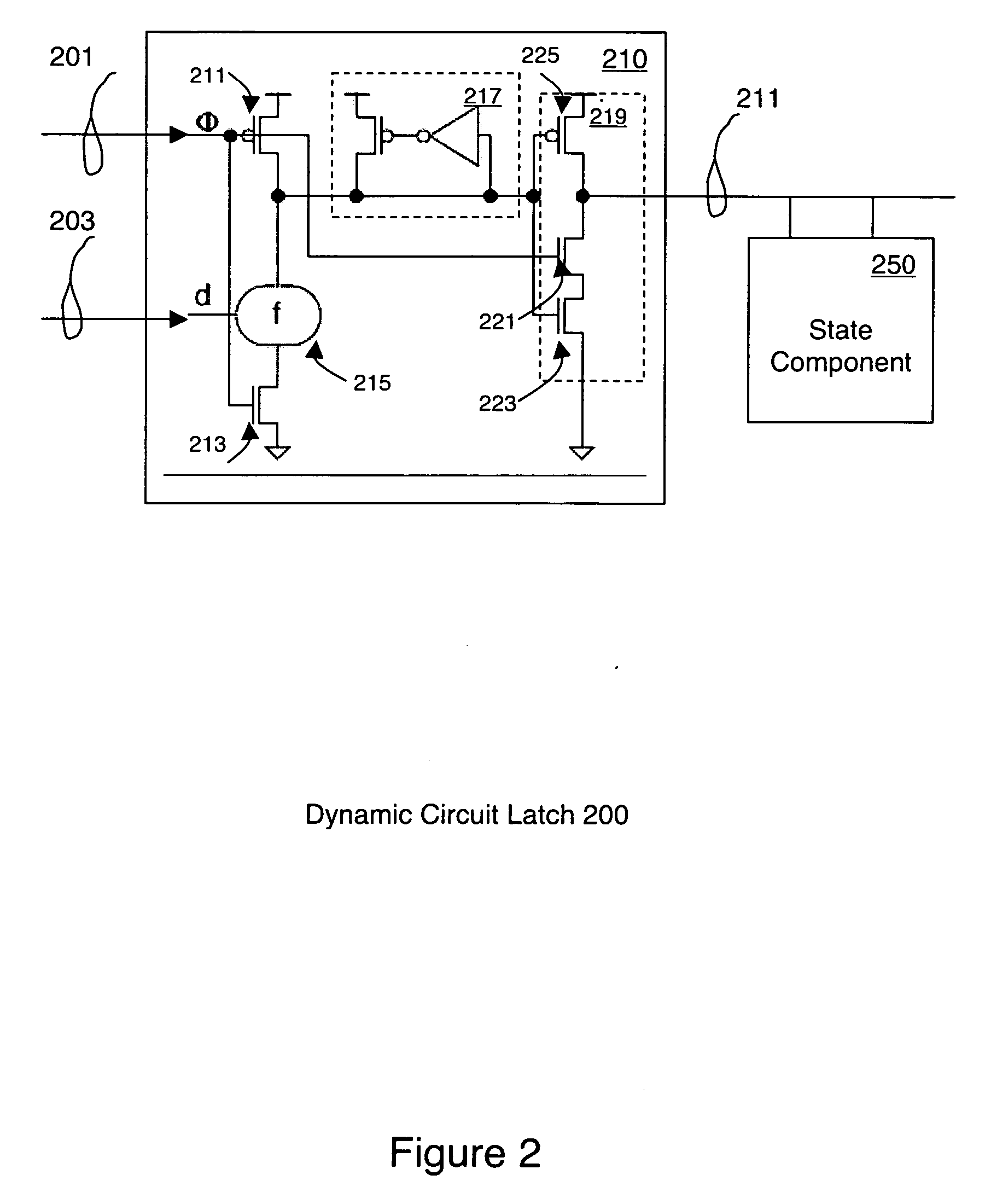
[0013] Scannable dynamic circuit latches are described. Reference will now be made in detail to several embodiments of the invention. While the invention will be described in conjunction with the alternative embodiment(s), it will be understood that they are not intended to limit the invention to these embodiments. On the contrary, the invention is intended to cover alternative, modifications, and equivalents, which may be included within the spirit and scope of the invention as defined by the appended claims.

[0014] Furthermore, in the following detailed description of the present invention, numerous specific details are set forth in order to provide a thorough understanding of the present invention. However, it will be recognized by one skilled in the art that the present invention may be practiced without these specific details or with equivalents thereof. In other instances, well-known methods, procedures, components, and circuits have not been described in detail as not to unne...


PUM


Abstract

A dynamic circuit latch, having the functionality of a domino circuit and a transparent latch, without the delay associated with the inclusion of a separate series latch element. Embodiments include a fast scannable footed Domino dyanmic latch. Also described is a fast scannable delay reset Domino dynamic latch. A fast scannable compound Domino dynamic latch is also described.

Description

BACKGROUND [0001] 1. Field of the Invention [0002] Embodiments of this invention relate generally to the field of latches, and more specifically to latches well-suited to use with domino circuits. [0003] 2. Related Art [0004] In high-speed integrated circuit (IC) applications, particularly microprocessors and microcontrollers, Domino circuits are used, where appropriate, to provide speed advantages over static logic. Such applications rarely include scannable latches for similar reasons, e.g., the inclusion of a scannable latch inserts substantial delay into the circuit. In order to provide full scan support, a circuit includes static latches twice per cycle, and the clocks are shut down twice per cycle, in order to avoid conflicts. While scannable latches are desirable, in order to allow for improved logic testing than is otherwise possible, the delay imposed is too significant. SUMMARY [0005] A dynamic circuit latch, having the functionality of a domino circuit and a transparent l...

Claims


Application Information

Patent Timeline
Patent Type & Authority Applications(United States)
IPC IPC(8): H03K19/096
CPCH03K19/0963
Inventor MASLEID, ROBERT PAULSOUSA, JOSEKOTTAPALLI, VENKATA
Owner INTELLECTUAL VENTURES HOLDING 81 LLC
Why Eureka
Try Eureka