Heat exchangers with corrugated heat exchange elements of improved strength

a technology of heat exchange elements and corrugated sheets, which is applied in the direction of tubular elements, lighting and heating apparatuses, laminated elements, etc., can solve the problems of poor heat transfer, limited heat transfer, and relatively large space between adjacent side walls

Inactive Publication Date: 2007-01-18
DANA CANADA CORP
View PDF31 Cites 116 Cited by
  • Summary
  • Abstract
  • Description
  • Claims
  • Application Information

AI Technical Summary

Problems solved by technology

One disadvantage of the Joshi turbulizer is that the triangular or V-shaped corrugations make contact with the plates only along the relatively narrow top and bottom surfaces of the turbulizer, thereby limiting heat transfer.
Furthermore, the sloping side walls of the Joshi turbulizer result in the formation of relatively large spaces between adjacent side walls.
Where the corrugations are aligned parallel to the direction of fluid flow, there is significant duct flow between the side walls, which results in poor heat transfer.
The metal foil used in these inserts is very thin and therefore it is difficult to form clean bends along the edges of the top and bottom walls.
Due to the thinness of the foil, the heat exchange elements can be easily crushed by this compression, resulting in irreparable damage to the heat exchanger.
While the strength of the corrugated heat exchange element may be improved by the provision of louvers, this improvement is sometimes insufficient to resist crushing during assembly.
Furthermore, in conventional louvered fins or turbulizers as taught by Joshi, there is an unsupported area between the ends of the louvers and the top and bottom walls.
This unsupported area is particularly vulnerable to crushing during assembly of the heat exchanger.

Method used


Image

  • Heat exchangers with corrugated heat exchange elements of improved strength
  • Heat exchangers with corrugated heat exchange elements of improved strength
  • Heat exchangers with corrugated heat exchange elements of improved strength

Examples


Embodiment Construction

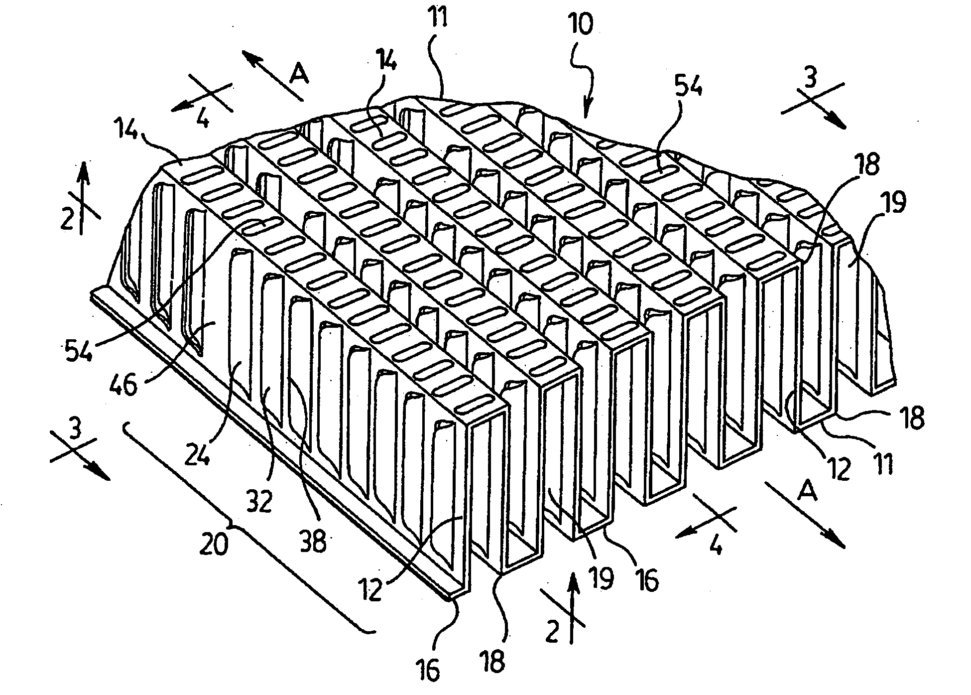
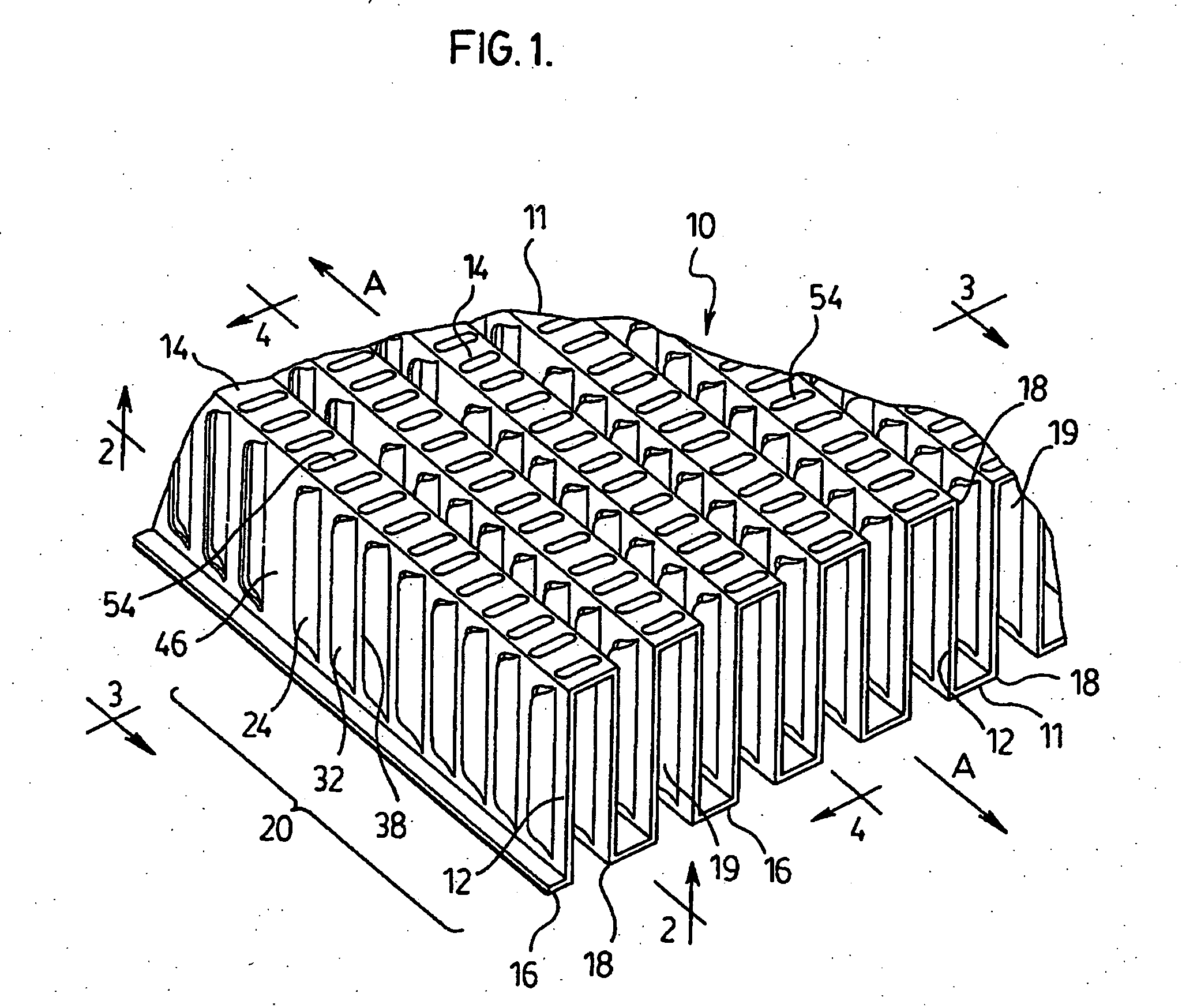
[0032] The following is a detailed description of preferred corrugated heat exchange elements according to the invention, as well as preferred heat exchangers in which they are used. As used herein, the term “corrugated heat exchange element” is intended to include both corrugated fins and turbulizers which, as mentioned above, are structurally similar and differ primarily in the way they are incorporated into heat exchangers.

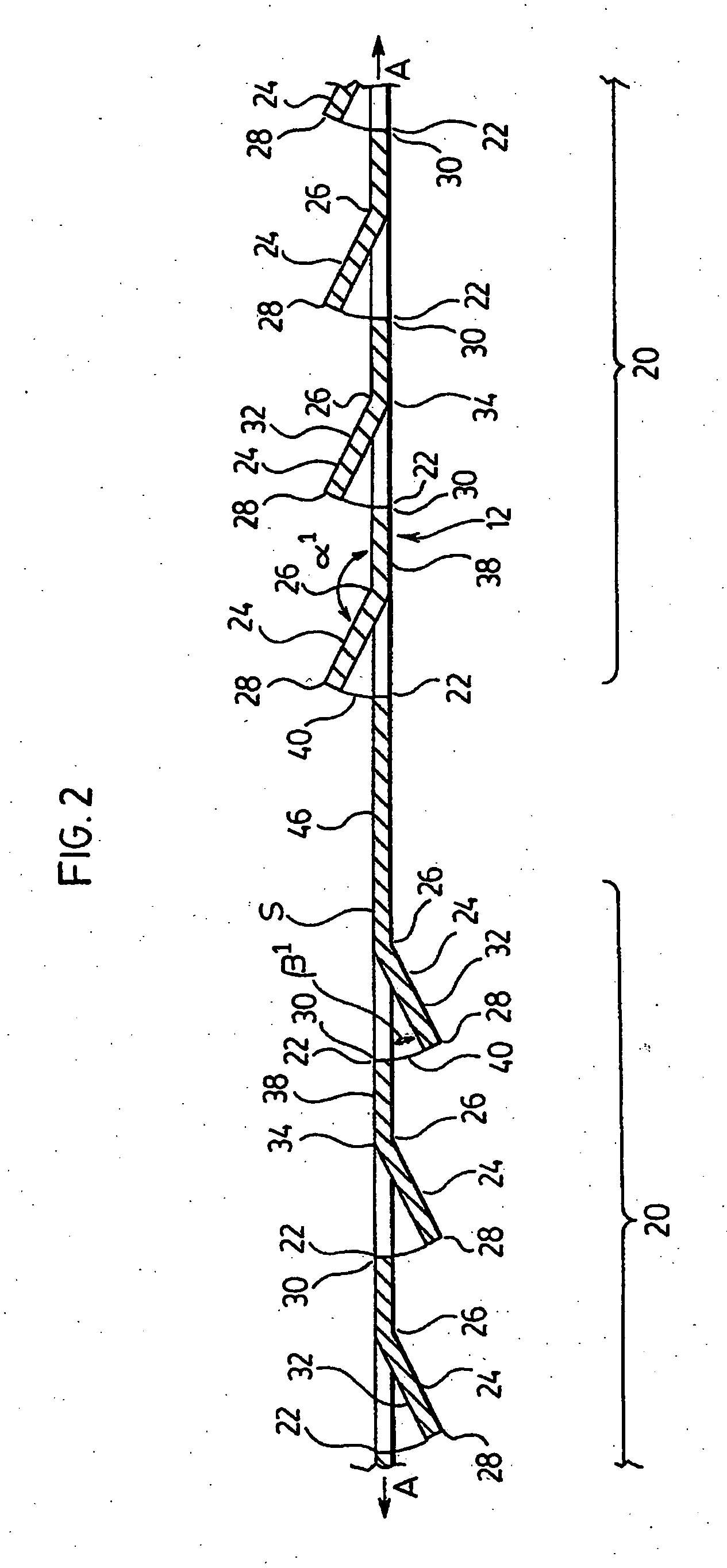
[0033] A first preferred corrugated heat exchange element 10 according to the invention is now described with reference to FIGS. 1 to 4. Heat exchange element 10 comprises a plurality of corrugations 11 extending along a longitudinal axis A, the corrugations 11 being defined by a plurality of spaced-apart side walls 12 interconnected by a plurality of top and bottom walls 14, 16. Each side wall 12 defines a plane S (FIG. 2) and extends parallel to axis A. Each of the side walls 12 has a height H and extends between an adjacent top wall 14 and an adjacent botto...


PUM


Abstract

A corrugated fin or turbulizer for a heat exchanger comprises a series of corrugations with parallel side walls. The side walls are provided with a series of parallel slits between which one-sided or two-sided louvers are defined. Each of the louvers has first and second edges extending along an adjacent pair of slits, and at least one bend located between the edges, thereby causing at least one of the edges of the louver to project outwardly of the plane of the side wall, and providing the side wall with improved crush resistance. The corrugations may preferably be rectangular or trapezoidal in form, having generally flat top and bottom surfaces defined by two closely-spaced bends. The top and bottom surfaces may preferably be provided with protrusions, at least some of which extend close to the bends. This assists in creating localized areas of weakness along which the bends can be formed cleanly.

Description

FIELD OF THE INVENTION [0001] The invention relates to heat exchangers and corrugated heat exchange elements for use therein, and particularly to corrugated heat exchanger fins and turbulizers of improved strength and manufacturability, and to heat exchangers incorporating such fins and turbulizers. BACKGROUND OF THE INVENTION [0002] Heat exchangers are commonly provided with heat exchange elements such as corrugated fins and / or turbulizers in order to enhance heat transfer between two or more fluids. Corrugated fins and turbulizers are structurally similar, and typically comprise a thin metal sheet in which parallel bends define a series of corrugations of a generally rectangular or triangular form. A turbulizer is generally inserted inside a fluid flow passage defined by the interior of a tube or a plate pair, whereas a fin is generally mounted on an exterior surface of a tube or plate pair. The fluids which come into contact with these heat exchange elements may be on the hot or ...

Claims


Application Information

Patent Timeline
Patent Type & Authority Applications(United States)
IPC IPC(8): F28F13/12
CPCF28F3/027F28F1/128
Inventor DUKE, BRIAN E.CARON, RAYMOND R.COTTON, JAMES S.GERGES, IHAB E.KOZDRAS, MARK S.
Owner DANA CANADA CORP
Why Eureka
Try Eureka