Shoe tensioning linkage for meat skinner

Active Publication Date: 2007-02-01
STORK TOWNSEND BV
View PDF16 Cites 9 Cited by
  • Summary
  • Abstract
  • Description
  • Claims
  • Application Information

AI Technical Summary

Benefits of technology

[0009] A skinning machine includes a frame, a linkage assembly mounted to the frame, and a skinning assembly mounted to the linkage assembly via lift arms. The linkage assembly is adapted to raise and lower the skinning assembly via the lift arms from an open position for cleaning to a closed position for skinning, wherein the linkage assembly is located on one side of the skinning assembly. A spring cartridge is operatively associated with the lift arms via an intermediate link, wherein the intermediate link is adapted to equally apply bias force from the spring cartridge to the independently rotatable lift arms.
[0010] A release lever is rotatably mounted on the frame

Problems solved by technology

Not only does this manual method require substantial labor, but it also is time consuming and creates safety hazards with the potential for lacerations and cumulative trauma injuries.
Alternatively, automated systems have been used to remove the skin and/or fat, but these conventional automated systems have an abundance of parts with a great number of wear points, and also have insufficient means for properly balancing the force on both si

Method used


Image

  • Shoe tensioning linkage for meat skinner
  • Shoe tensioning linkage for meat skinner
  • Shoe tensioning linkage for meat skinner

Examples


Embodiment Construction

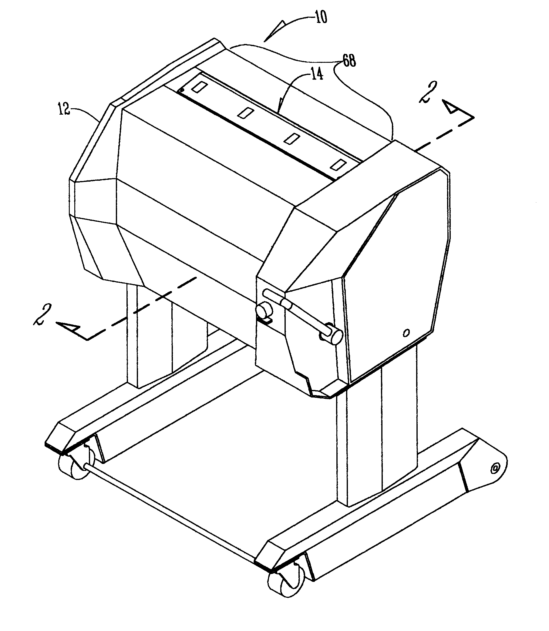
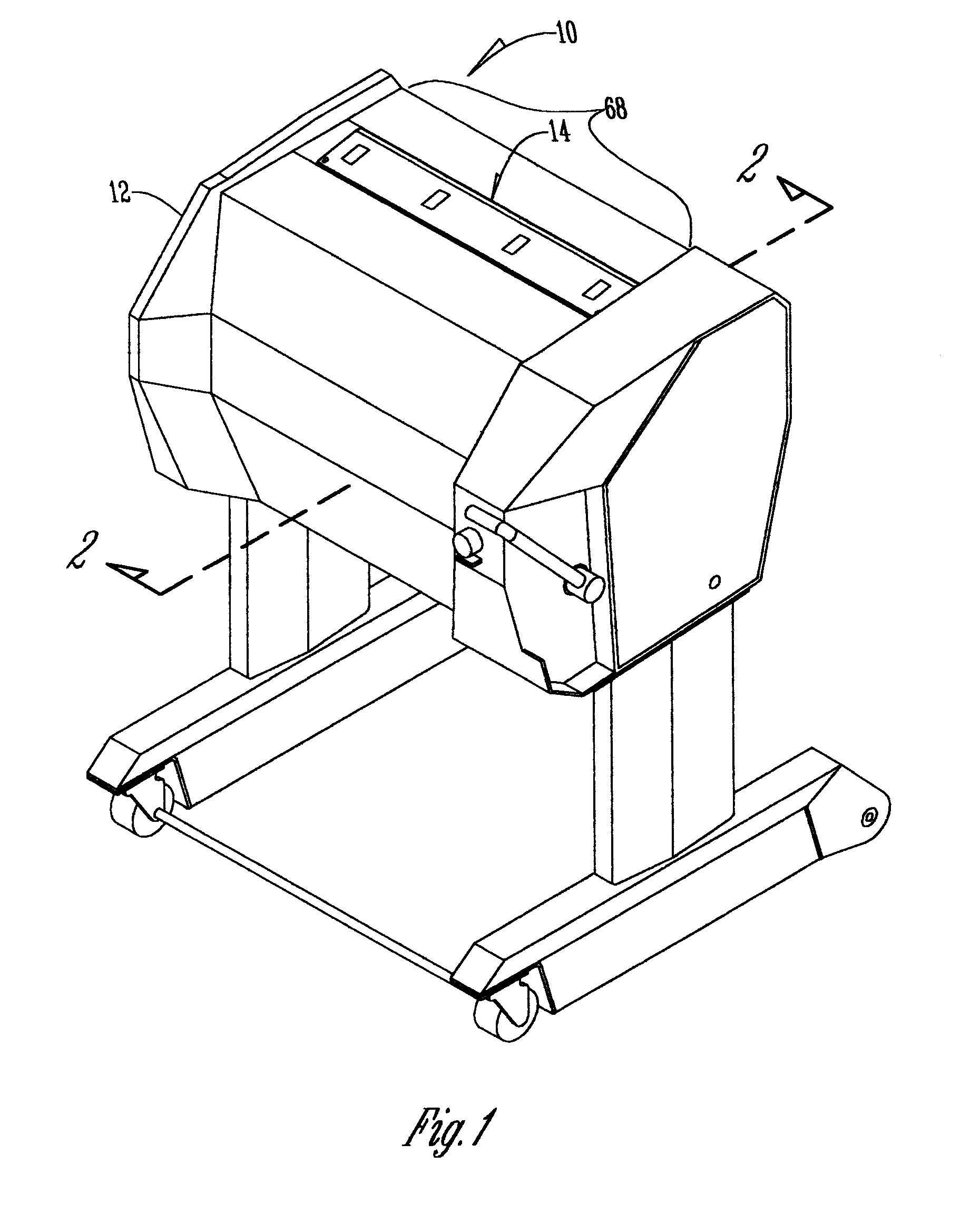
[0017] Referring to FIGS. 1 and 2, a skinning machine 10 has a frame 12 with a skinning assembly 14 and a toothroll 16 operatively associated with the frame 12. The toothroll 16 is rotatably mounted to the frame 12. The toothroll 16 is driven by a drive mechanism (not shown). The drive mechanism includes but is not limited to, any conventional drive device operatively connected to a power source (not shown).

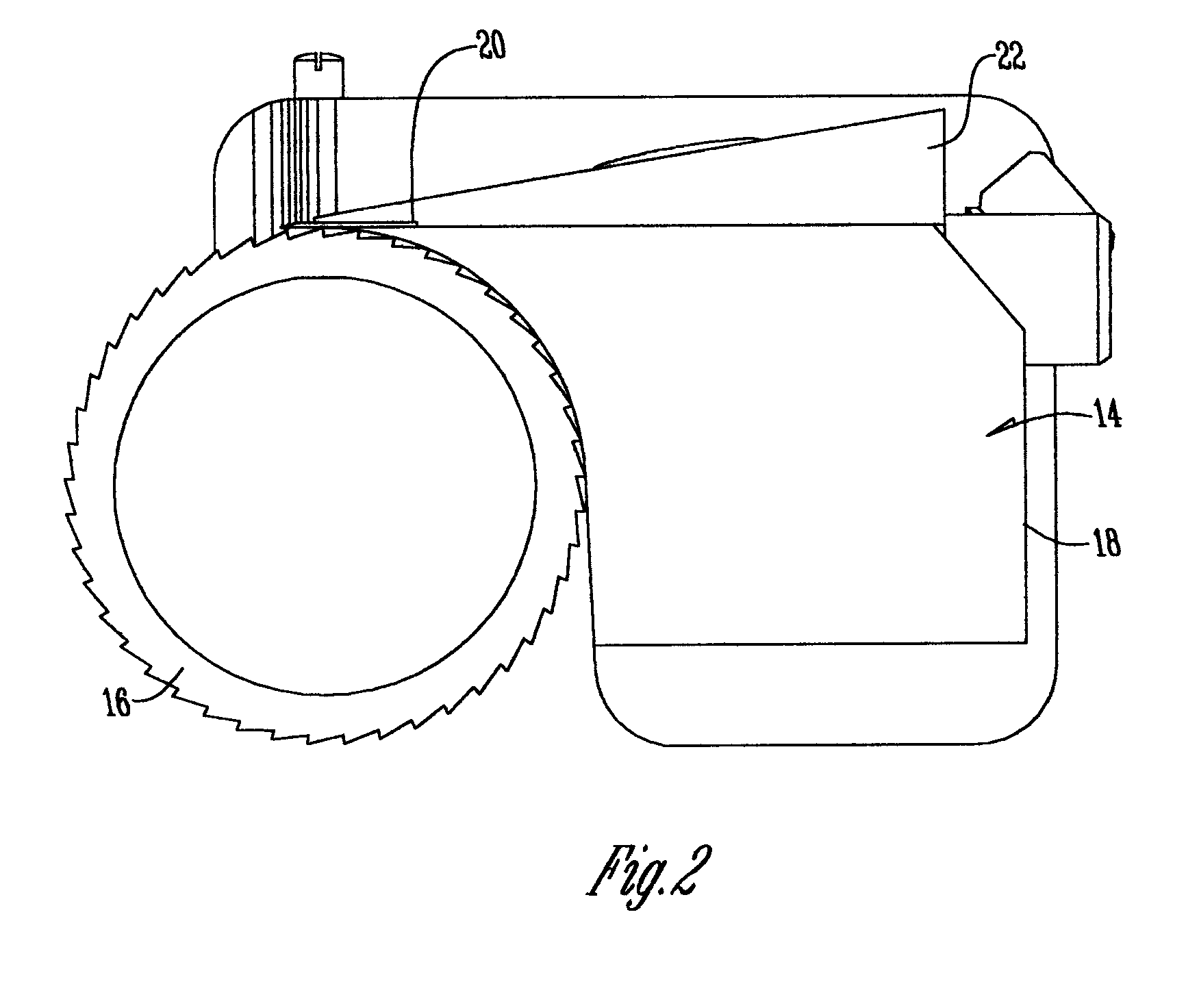
[0018] The skinning assembly 14 is positioned in spaced relation to the toothroll 16. The skinning assembly 14 includes a shoe 18 with a blade clamp 22 attached thereto for receiving and holding a skinning blade 20. The skinning blade 20 is positioned between the shoe 18 and the clamp 22 such that blade 20 is adjacent the radial surface of the toothroll 16. The toothroll 16 assists in directing a layer of skin and / or fat of a meat part (not shown) between the shoe 18 and the toothroll 16. The toothroll 16, shoe 18, and skinning blade 20 remove the skin and / or fat from the meat p...


PUM


Abstract

A skinning machine includes a frame, a linkage assembly mounted to the frame, and a skinning assembly mounted to the linkage assembly via lift arms. The linkage assembly raises and lowers the skinning assembly via the lift arms from an open to a closed position, wherein the linkage assembly is located on one side of the skinning assembly. A spring cartridge is operatively associated with the lift arms via an intermediate link to equally apply bias force from the spring cartridge to the independently rotatable lift arms. The linkage assembly includes a cam slot provided through a cam arm to slidably receive a pin therein. The cam slot is shaped to lock the pin when the linkage assembly is in the closed position. A cam block is mounted to the frame and includes a cam notch adapted to slidably secure the end of the pin in a locked open position.

Description

BACKGROUND OF THE INVENTION [0001] This invention is directed toward skinning machines for removing skin and fat from meat parts, and more particularly toward a skinning machine that has a linkage assembly adapted to raise and lower a skinning assembly on the skinning machine. [0002] In the meat processing industry, it is necessary and desirable to remove the skin and / or fat from a meat part, before separating the muscles for processing. To date, this is often done manually, using knives. Not only does this manual method require substantial labor, but it also is time consuming and creates safety hazards with the potential for lacerations and cumulative trauma injuries. Alternatively, automated systems have been used to remove the skin and / or fat, but these conventional automated systems have an abundance of parts with a great number of wear points, and also have insufficient means for properly balancing the force on both sides of the skinning assembly. [0003] Specifically, typical a...

Claims


Application Information

Patent Timeline
IPC IPC(8): A22B5/16
CPCA22B5/166
Inventor BERGMAN, MATTHEW A.LEBSACK, KENNETH L.MYERS, JAMES L.SAWHILL, MATTHEW P.VELDKAMP, BRENT M.
Owner STORK TOWNSEND BV
Why Eureka
Try Eureka