Ink jet head driving method and apparatus
- Summary
- Abstract
- Description
- Claims
- Application Information
AI Technical Summary
Benefits of technology
Problems solved by technology
Method used
Image
Examples
Embodiment Construction
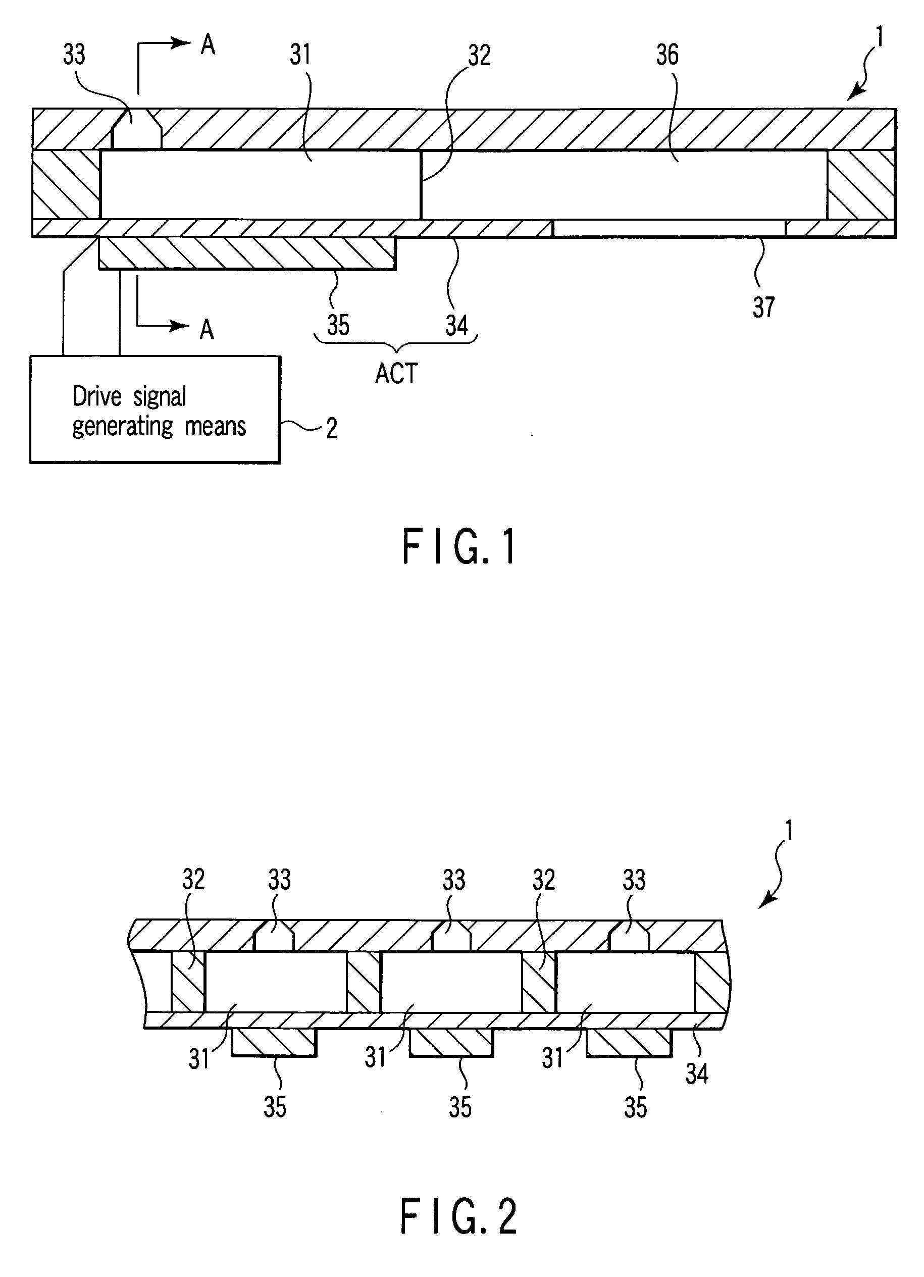
[0033] Hereinafter, an embodiment of the present invention will be described with reference to the accompanying drawings. FIGS. 1 and 2 are views each showing a construction of essential portions in an ink jet printing apparatus. FIG. 2 is a sectional view taken along the line A-A of FIG. 1.
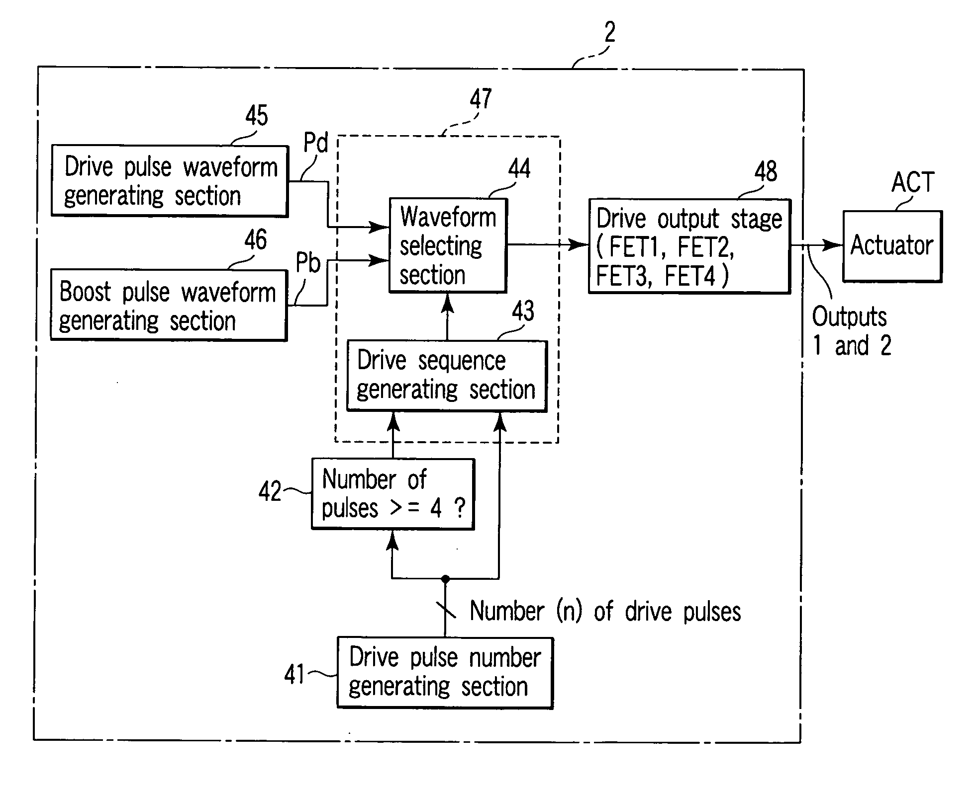
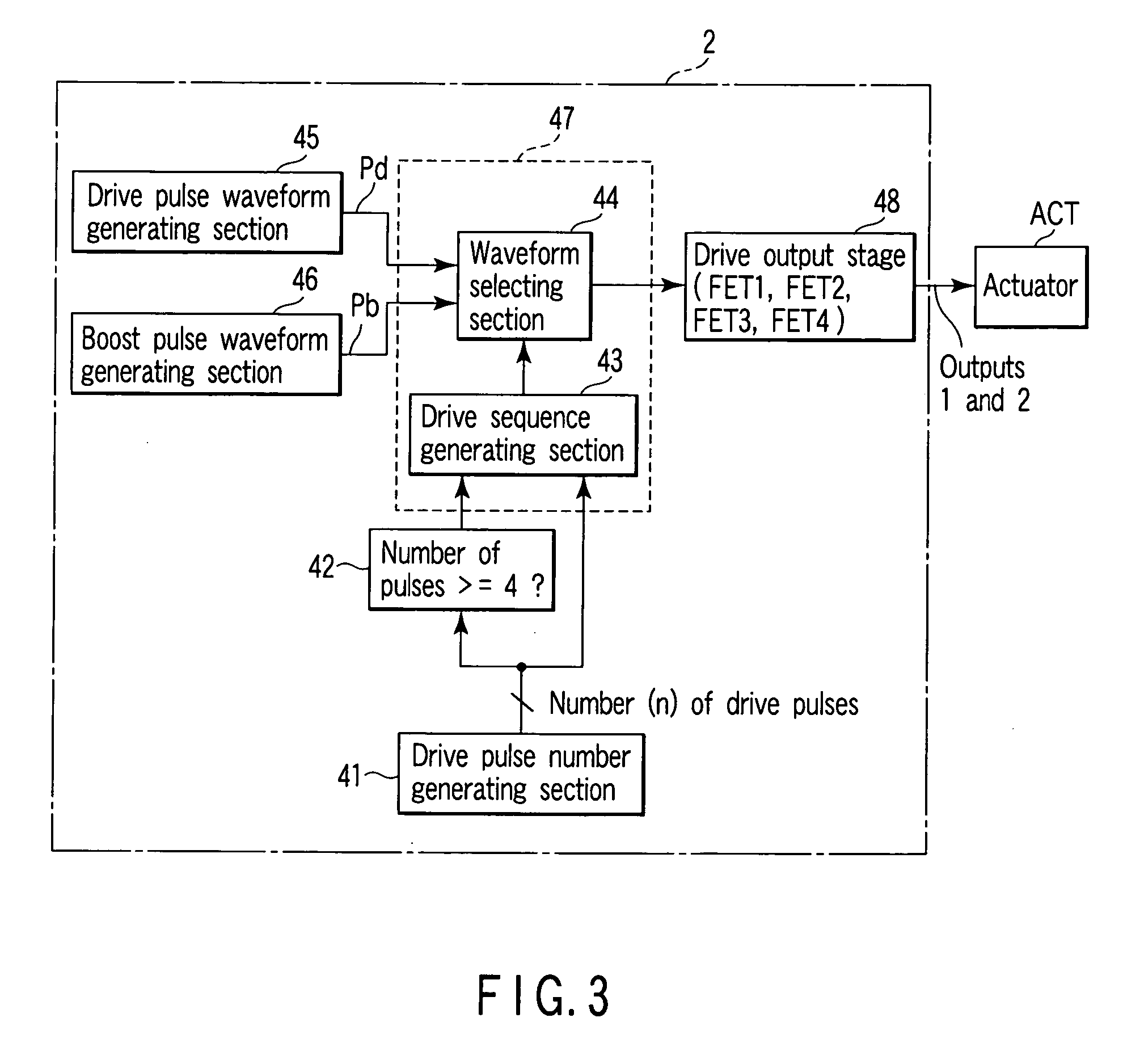
[0034] In FIGS. 1 and 2, reference numeral 1 denotes an ink jet head; and reference numeral 2 denotes drive signal generating means. The ink jet head 1 is formed while a plurality of pressure chambers 31 housing ink is partitioned by a bulkhead 32, and nozzles 33 for ejecting ink droplets are provided in the pressure chamber 31, respectively. A bottom face of each of the pressure chambers 31 is formed of a vibration plate 34, and a plurality of piezoelectric members 35 is fixed in correspondence with each of the pressure chambers at the lower face side of the vibration plate 34. The vibration plate 34 and the piezoelectric member 35 constitute an actuator ACT, and the piezoelectric member is ele...
PUM
 Abstract
Description
Claims
Application Information
 - R&D
- Intellectual Property
- Life Sciences
- Materials
- Tech Scout
- Unparalleled Data Quality
- Higher Quality Content
- 60% Fewer Hallucinations
Browse by: Latest US Patents, China's latest patents, Technical Efficacy Thesaurus, Application Domain, Technology Topic, Popular Technical Reports.
© 2025 PatSnap. All rights reserved.Legal|Privacy policy|Modern Slavery Act Transparency Statement|Sitemap|About US| Contact US: help@patsnap.com


