
Child seat

a child seat and seat technology, applied in the field of child seats, can solve the problems of considerable difficulty in operation or inability to perform height adjustment of webbing, and achieve the effect of easy adjustment of webbing height and easy adjustment of sliding member heigh

Inactive Publication Date: 2007-02-22
TAKATA CORPORATION
View PDF24 Cites 21 Cited by
  • Summary
  • Abstract
  • Description
  • Claims
  • Application Information

AI Technical Summary

Benefits of technology

[0011] In the child seat of the present invention, the movable body for changing the height of the sliding member is operable to move from the side of the backrest portion. Accordingly, even when the child seat is provided toward the front side of the vehicle seat and the like, it is possible to easily adjust the height of the webbing.
[0012] In the child seat of the second aspect, by engaging the locking portion and the engaging portion by means of the operation of the operating piece, it is possible to lock the movable body in a desired height. By disengaging both locking portion and engaging portion, it is possible to move the sliding member and all of the movable bodies vertically. Under this state, when the handle is turned, the movable body and the sliding member move vertically. After moving to the desired height, the movable body is locked by operating the operating piece. Therefore, in the second aspect, it is possible very easily to adjust the height of the sliding member.
[0014] In the child seat of the fourth aspect, since the left and right movable bodies are interlocked, even when it is operated only from the left side or only from the right side of the child seat, it is possible to move the movable bodies on both sides smoothly.

Problems solved by technology

Accordingly, when the child seat is fixed toward a front side of the vehicle seat, the height adjustment of the webbing cannot be performed or is considerably difficult to operate.

Method used


Image

  • Child seat
  • Child seat
  • Child seat

Examples


Embodiment Construction

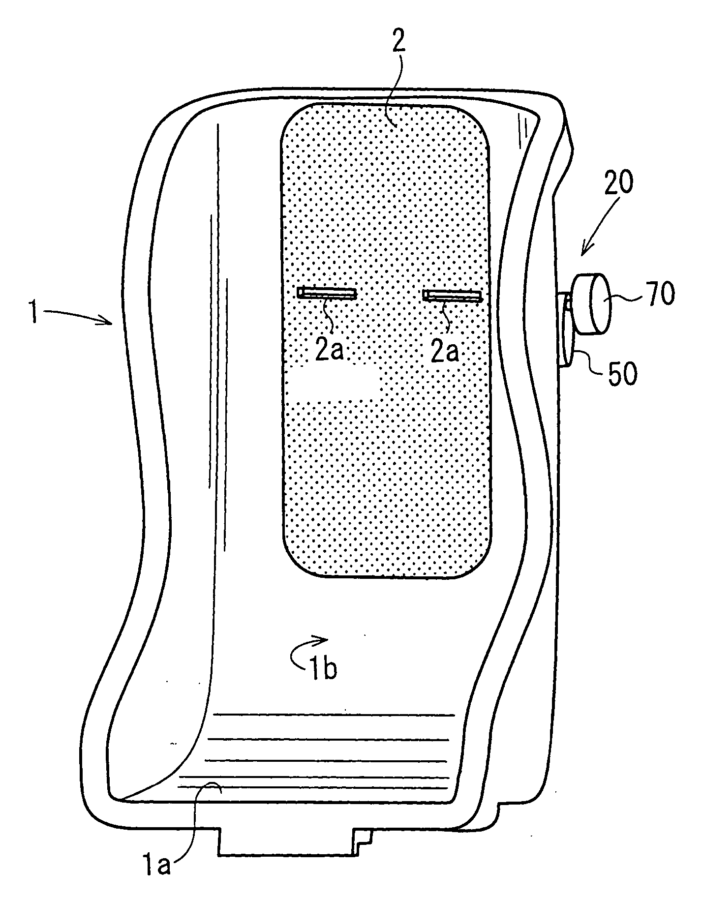
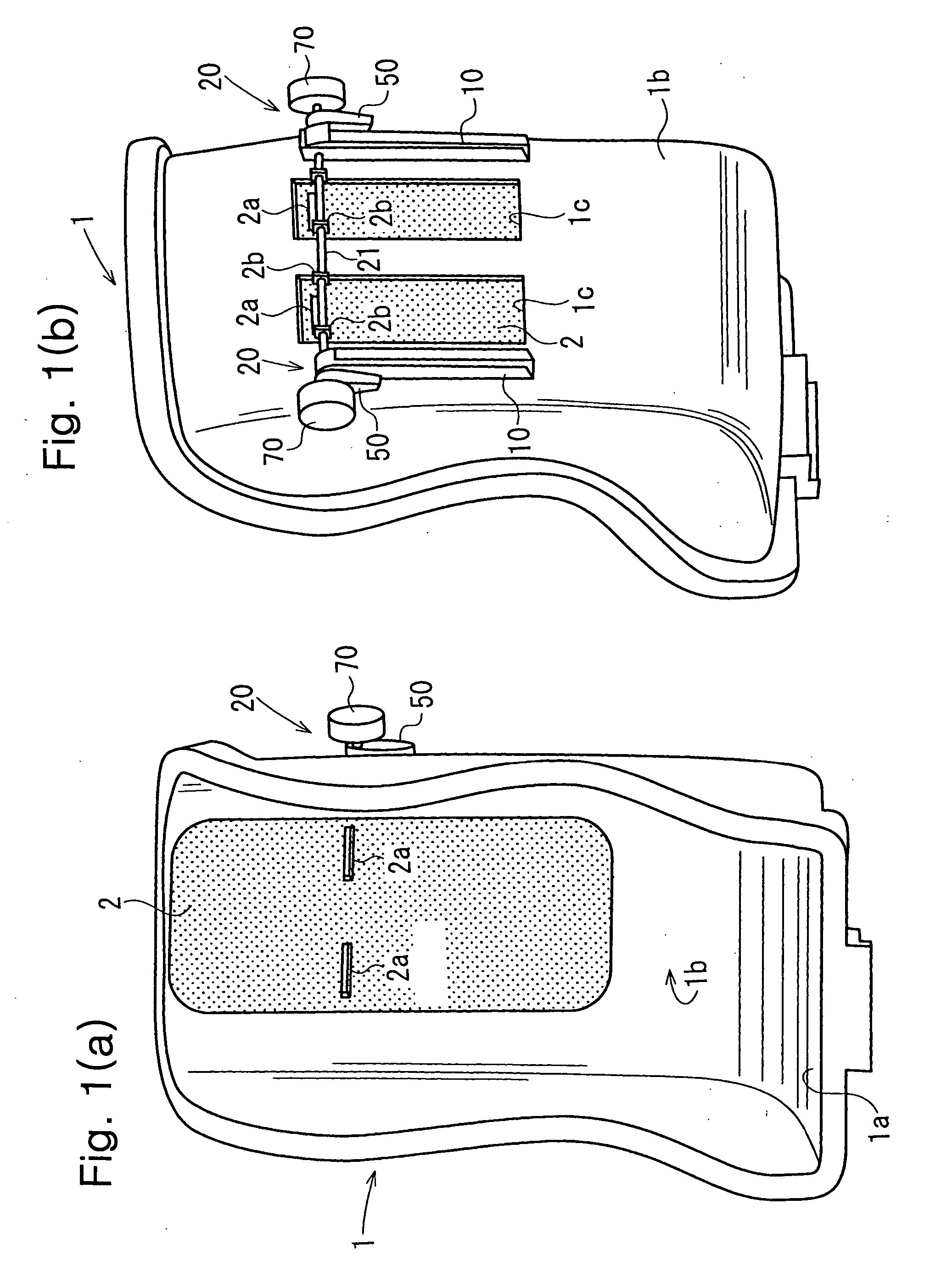
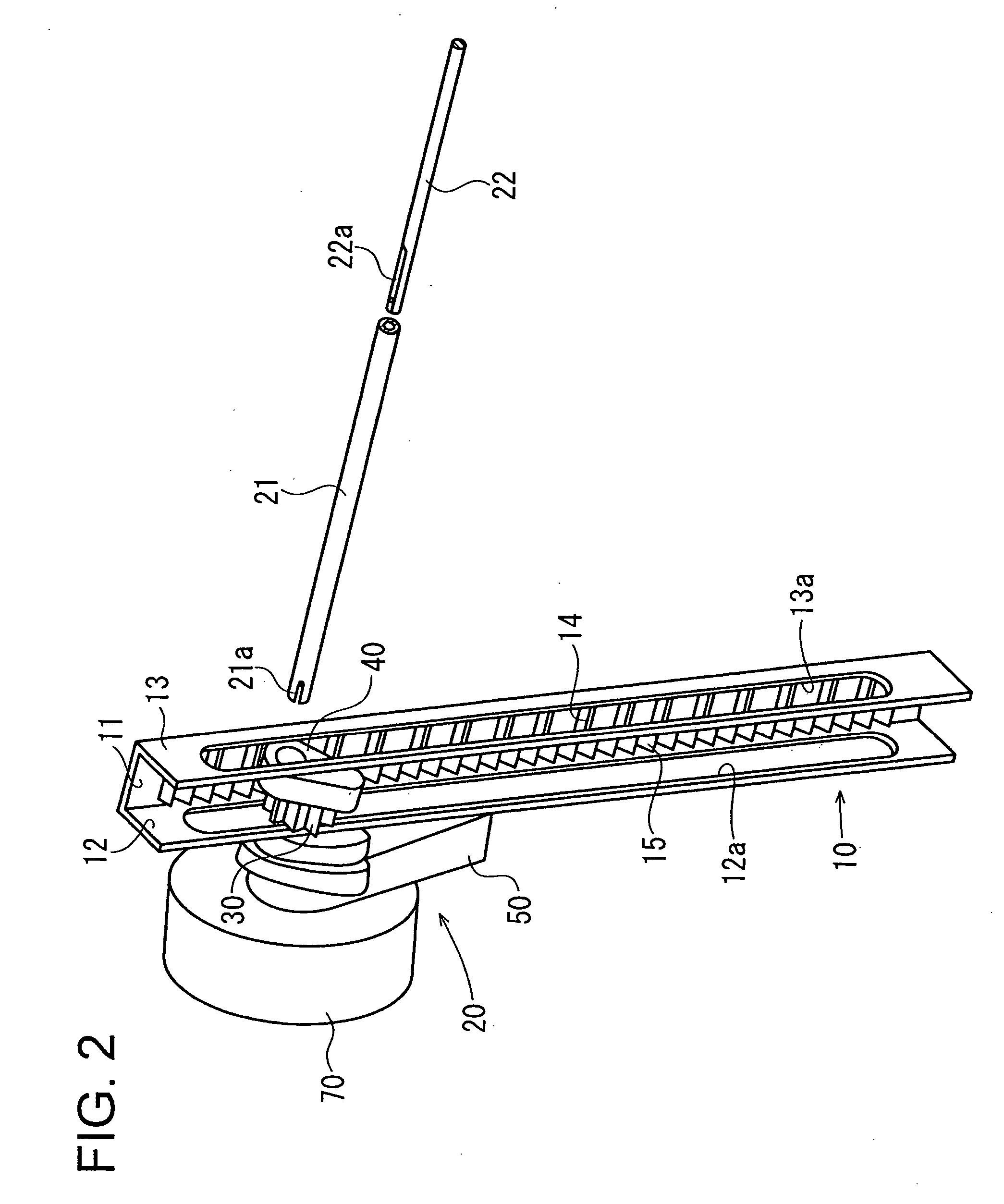
[0021] Hereinafter, an embodiment will be explained with reference to drawings. FIG. 1(a) is a front perspective view of a seat main body of a child seat according to an embodiment, and FIG. 1(b) is a rear perspective view of thereof. FIG. 2 is a perspective view of a guide rail and a movable body. FIG. 3(a) is a horizontal cross-sectional view of a guide rail and FIGS. 3(b) and 3(c) are cross-sectional views taken along lines 3(b)-3(b) and 3(c)-3(c) in FIG. 3(a), respectively. FIGS. 4, 5 and 6 are exploded perspective views of the movable body.

[0022] The seat main body 1 has a seat portion la and a backrest portion 1b. The seat main body 1 forms the child seat mounted on a base member (not shown) to be reclined.

[0023] In the backrest portion 1b, vertically extending perforated holes 1c are provided on the right side and on the left side respectively, and in order to block the perforated holes, a sliding member 2 of a plate shape is provided on the front side of the backrest porti...


PUM


Abstract

A child seat includes a main body having a seat portion and a backrest portion with a hole therein, a sliding member disposed at the backrest portion to cover the hole and having webbing inserting holes, and a guide rail mounted vertically on a rear side of the main body. A movable body is attached to the sliding member to move along the guide rail. The movable body is disposed on the rear side to be operable from a side of the backrest portion.

Description

BACKGROUND OF THE INVENTION AND RELATED ART STATEMENT [0001] The present invention relates to a child seat provided on a seat of a vehicle and the like, particularly, to the child seat having a height adjusting device for a webbing laid on a child sitting on the child seat. [0002] A child seating on a child seat is restrained with the child seat by a webbing provided on the child seat. [0003] In the Japanese Unexamined Patent Application Publication No. 2004-331055, there is disclosed a child seat, in which a sliding member having webbing inserting holes (hereinafter, referred to as a locking body) is provided on a backrest portion of the child seat to vertically move, and the height of the webbing can be adjusted by moving the sliding member. [0004] In a child seat in Japanese Unexamined Patent Application Publication No. 2004-331055, the height of a webbing can be adjusted only from the rear side of a backrest portion. Accordingly, when the child seat is fixed toward a front side ...

Claims


Application Information

Patent Timeline
IPC IPC(8): A47D1/10B60N2/16A47D15/00A62B35/00
CPCB60N2/2812B60N2/2851
Inventor SAKUMOTO, MASAYUKI
Owner TAKATA CORPORATION
Learn More