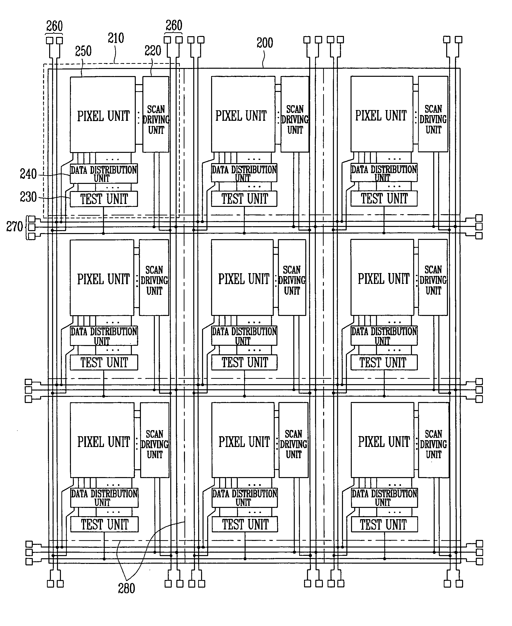
Organic electro luminescence display (OELD) to perform sheet unit test and testing method using the OELD
a luminescence display and organic technology, applied in the field of oeld, can solve problems such as reducing the efficiency of tes
- Summary
- Abstract
- Description
- Claims
- Application Information
AI Technical Summary
Benefits of technology
Problems solved by technology
Method used
Image
Examples
first embodiment
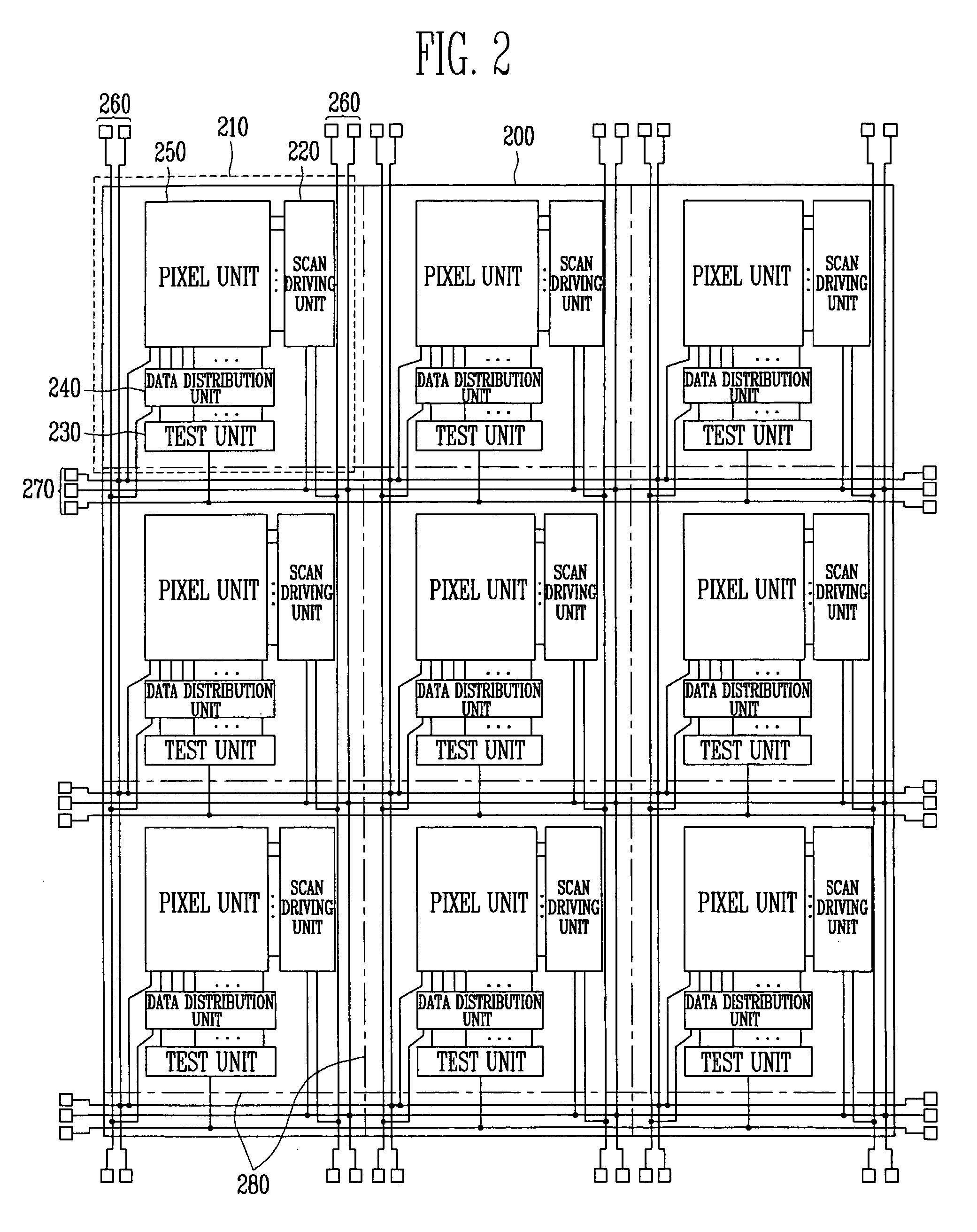
[0066]FIG. 3 is a view of the OELD and the wire groups of FIG. 2. The same parts as those of FIG. 2 have the same reference numerals, and their descriptions have been omitted below.
[0067] Referring to FIG. 3, the OELD 210 according to the first embodiment has the first wire group 260 and the second wire group 270 which include a plurality of wires.
[0068] The first wire group 260 includes a first wire 261 for receiving the first power supply voltage (ELVDD), second wires 262 for receiving at least two selected signals, third wires 263 for receiving the test control signals and the test signals, a fourth wire 264 for receiving the third power supply voltage (VDD), a fifth wire 265 for receiving the fourth power supply voltage (VSS), sixth wires 266 for receiving the scan control signals, and a seventh wire 267 for receiving the second power supply voltage (ELVSS).
[0069] The first wire 261 supplies the first power supply voltage (ELVDD), which is supplied during the sheet unit test, ...
second embodiment
[0088]FIG. 4 is a view of the OELD and the wire groups of FIG. 2. The same parts as in FIG. 2 have the same reference numerals, and therefore their descriptions have been omitted below.
[0089] Referring to FIG. 4, the OELD 210 according to the second embodiment has the first wire group 260 and the second wire group 270 which include a plurality of wires.
[0090] The first wire group 260 includes a first wire 261 for receiving the first power supply voltage (ELVDD), second wires 262 for receiving at least two selected signals, third wires 263 for receiving the test control signals and the test signals, a fourth wire 264 for receiving the third power supply voltage (VDD), a fifth wire 265 for receiving the fourth power supply voltage (VSS), sixth wires 266 for receiving the scan control signals, and a seventh wire 267 for receiving the second power supply voltage (ELVSS). The signals or the power supply voltages supplied to such a first wire group 260 are identical to those of FIG. 3, a...
third embodiment
[0105]FIG. 5 is a view of the OELD and the wire groups of FIG. 2. In the description of FIG. 5, the descriptions of the same parts as in FIG. 4 have been omitted below.
[0106] Referring to FIG. 5, the OELD 210 according to the third embodiment of the present invention has a transmission gate 275 connected to at least one of the wires included in the first wire group 260, and an eighteenth wire 278 and a nineteenth wire 279 included in the second wire group 270 to drive the transmission gate 275.
[0107] In the third embodiment of the present invention, the transmission gate 275 is connected to one of the wires included in the first wire group 260 to control whether or not the signals (or the power supply voltages)are supplied to the OELD 210 from the connected wires. For example, the transmission gate 275 can be positioned in any one of the sixth wires 266 for supplying the scan control signals. As described above, it is possible to conduct the test on the certain OELD in the motherbo...
PUM
 Abstract
Description
Claims
Application Information
 - R&D
- Intellectual Property
- Life Sciences
- Materials
- Tech Scout
- Unparalleled Data Quality
- Higher Quality Content
- 60% Fewer Hallucinations
Browse by: Latest US Patents, China's latest patents, Technical Efficacy Thesaurus, Application Domain, Technology Topic, Popular Technical Reports.
© 2025 PatSnap. All rights reserved.Legal|Privacy policy|Modern Slavery Act Transparency Statement|Sitemap|About US| Contact US: help@patsnap.com


