Formation evaluation system and method

a technology of formation evaluation and evaluation system, applied in the field of subterranean formation evaluation, can solve the problems of too high cost and too risky use of wirelines, and achieve the effect of reducing the risk of use and reducing the cost of us

Active Publication Date: 2007-03-08
SCHLUMBERGER TECH CORP
View PDF28 Cites 65 Cited by
  • Summary
  • Abstract
  • Description
  • Claims
  • Application Information

AI Technical Summary

Benefits of technology

[0022] The at least one parameter can be determined in a variety of different manners. For example, the at least one parameter can be determined by monitoring a control circuit of the downhole electromagnetic unit. In another version, the at least one parameter can be determined

Problems solved by technology

The use of a wireline can be too risky to

Method used


Image

  • Formation evaluation system and method
  • Formation evaluation system and method
  • Formation evaluation system and method

Examples


Embodiment Construction

[0032] Presently preferred embodiments of the invention are shown in the above-identified figures and described in detail below. In describing the preferred embodiments, like or identical reference numerals are used to identify common or similar elements. The figures are not necessarily to scale and certain features and certain views of the figures may be shown exaggerated in scale or in schematic in the interest of clarity and conciseness.

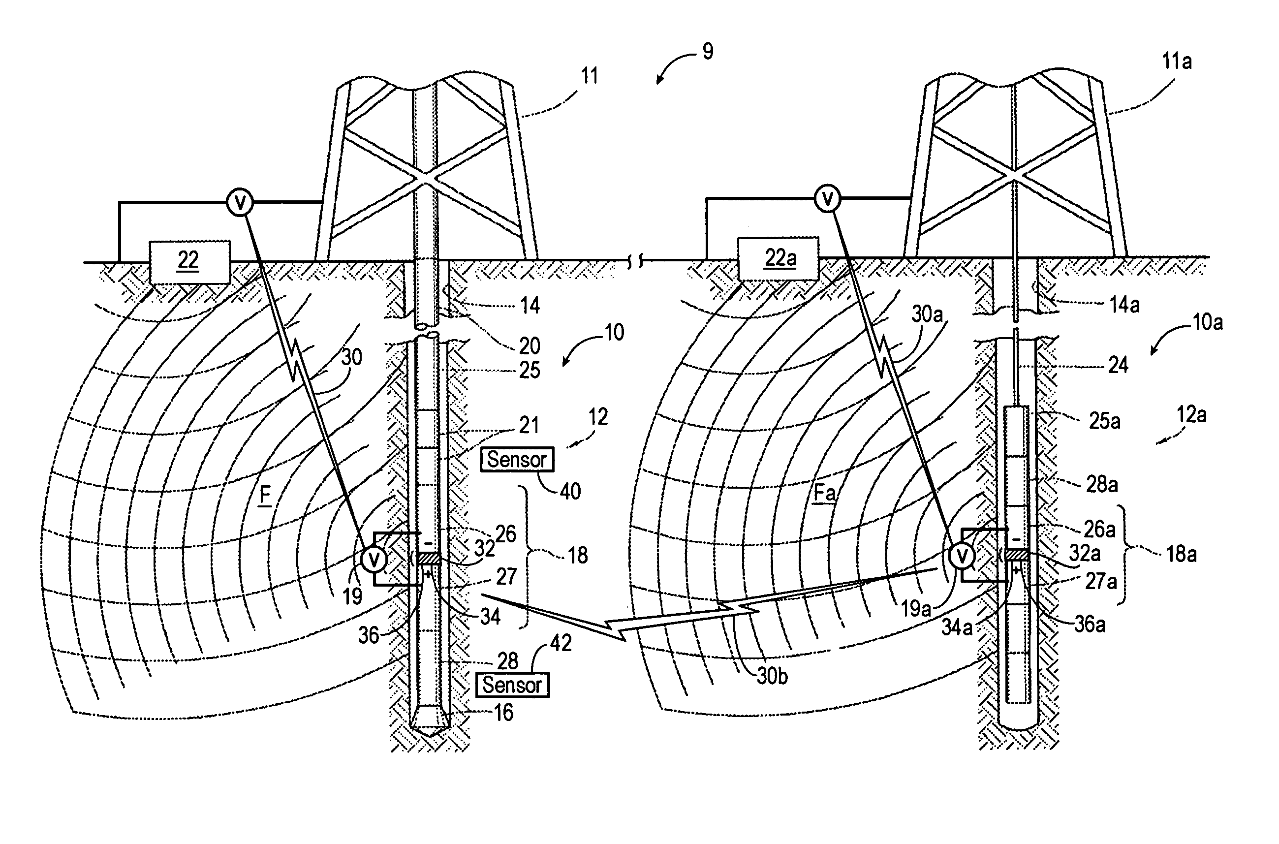
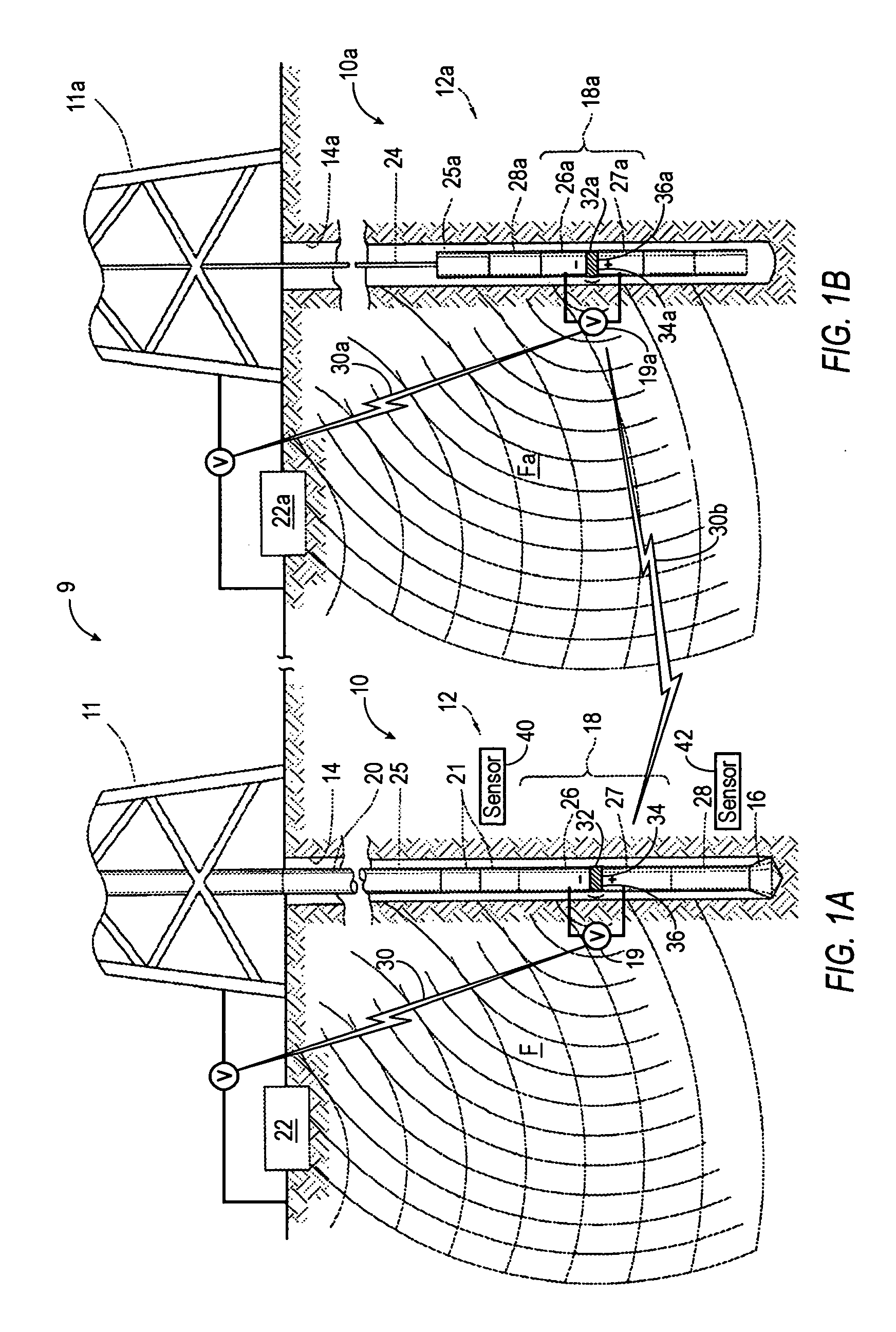
[0033]FIGS. 1A and 1B cooperate to illustrate a reservoir system 9 for evaluating at least one subterranean formation. FIG. 1A depicts a first electromagnetic system 10 used in cooperation with a downhole drilling tool 12, and FIG. 1B depicts a second electromagnetic system 10a used in cooperation with a downhole wireline tool 12a. The first electromagnetic system 10 is spaced a distance from the second electromagnetic system 10a. The first and second electromagnetic systems 10 and 10a can function separately or together to derive near-well bore ...


PUM


Abstract

A formation evaluation system for a subterranean formation penetrated by a wellbore. The formation evaluation system is provided with a downhole tool and a sensor. The downhole tool is positionable in the wellbore. The downhole tool has a downhole electromagnetic unit for communication with a surface electromagnetic unit. The sensor determines at least one wellsite parameter from the electromagnetic signal. The downhole tool and the surface electromagnetic unit are adapted to pass electromagnetic signals there between. The electromagnetic signals pass through the subterranean formation whereby the sensor determines the at least one wellsite parameter from the electromagnetic signal.

Description

BACKGROUND OF THE INVENTION [0001] The present invention relates to the evaluation of a subterranean formation penetrated by a wellbore. More particularly, the present invention relates to techniques for deriving at least one formation parameter from signals generated by a downhole tool positioned in the wellbore. [0002] The exploration of hydrocarbons involves placement of a downhole tool into the wellbore to perform various downhole operations. There are many types of downhole tools used in downhole operations. Typically, a drilling tool is suspended from an oil-rig and advanced into the earth to form the wellbore. The drilling tool may be a measurement-while-drilling (MWD) or a logging-while-drilling (LWD) tool adapted to perform downhole operations, such as taking measurements, during the drilling process. Such measurements are generally taken by instruments mounted within drill collars above the drill bit and may obtain information, such as the position of the drill bit, the na...

Claims


Application Information

Patent Timeline
IPC IPC(8): G01V3/00E21B47/13E21B47/12G01V3/38
CPCG01V11/002G01V3/28G01V3/30G01V3/34E21B47/125
Inventor LOVELL, JOHN R.BOGATH, CHRISTOPHER C.PRINGNITZ, STEVEN J.
Owner SCHLUMBERGER TECH CORP
Why Eureka
Try Eureka