Heat-induced transitions on a structured surface

a structure and transition technology, applied in the field of heat-induced transitions on a structured surface, can solve the problems of droplets not returning to their position on the top of the structure, existing surfaces do not provide adequate reversible control of wetting and dewetting,

Inactive Publication Date: 2007-03-15
ALCATEL LUCENT SAS
View PDF81 Cites 37 Cited by
  • Summary
  • Abstract
  • Description
  • Claims
  • Application Information

AI Technical Summary

Benefits of technology

[0007] To address the above-discussed deficiencies, one embodiment of the present invention is a device. The device comprises a substrate having a base layer, the base layer being connectable to a source of current. The device also includes fluid-support-structures located on the base layer. Each of the fluid-support-structures has at least one dimension of about 1 millimeter or less. The base layer is configured to impart heat to a fluid locatable over the base layer and convert at least a portion of the fluid to a vapor when a current is applied to the base layer.

Problems solved by technology

One problem encountered when handling small fluid volumes is to wet and de-wet a surface.
Unfortunately, existing surfaces do not provide adequate reversible control of wetting and de-wetting.
Unfortunately, the droplet may not return to its position on top of the structure, with its previous high contact angle, when the voltage is then turned off.
Another problem encountered when handling small fluid volumes is to effectively mix fluids together.
Poor mixing can occur in channel-based microfluidic devices, where two or more volumes of different fluids, each flowing through microchannels, are combined together at a junction and into a single channel.
However, flow diverters are complex structures that are technically difficult to construct.
Additionally, channels having flow diverters are prone to being clogged by particles suspended in the fluid.
Poor mixing can also occur in droplet-based microfluidic devices, where the fluids are not confined in channels.
In such cases, there is limited ability to mix two droplets together because there is no flow of fluids to facilitate mixing.
Additionally, because there is no flow of fluids, it is not possible to facilitate mixing with the use of flow diverters.

Method used


Image

  • Heat-induced transitions on a structured surface
  • Heat-induced transitions on a structured surface
  • Heat-induced transitions on a structured surface

Examples


Embodiment Construction

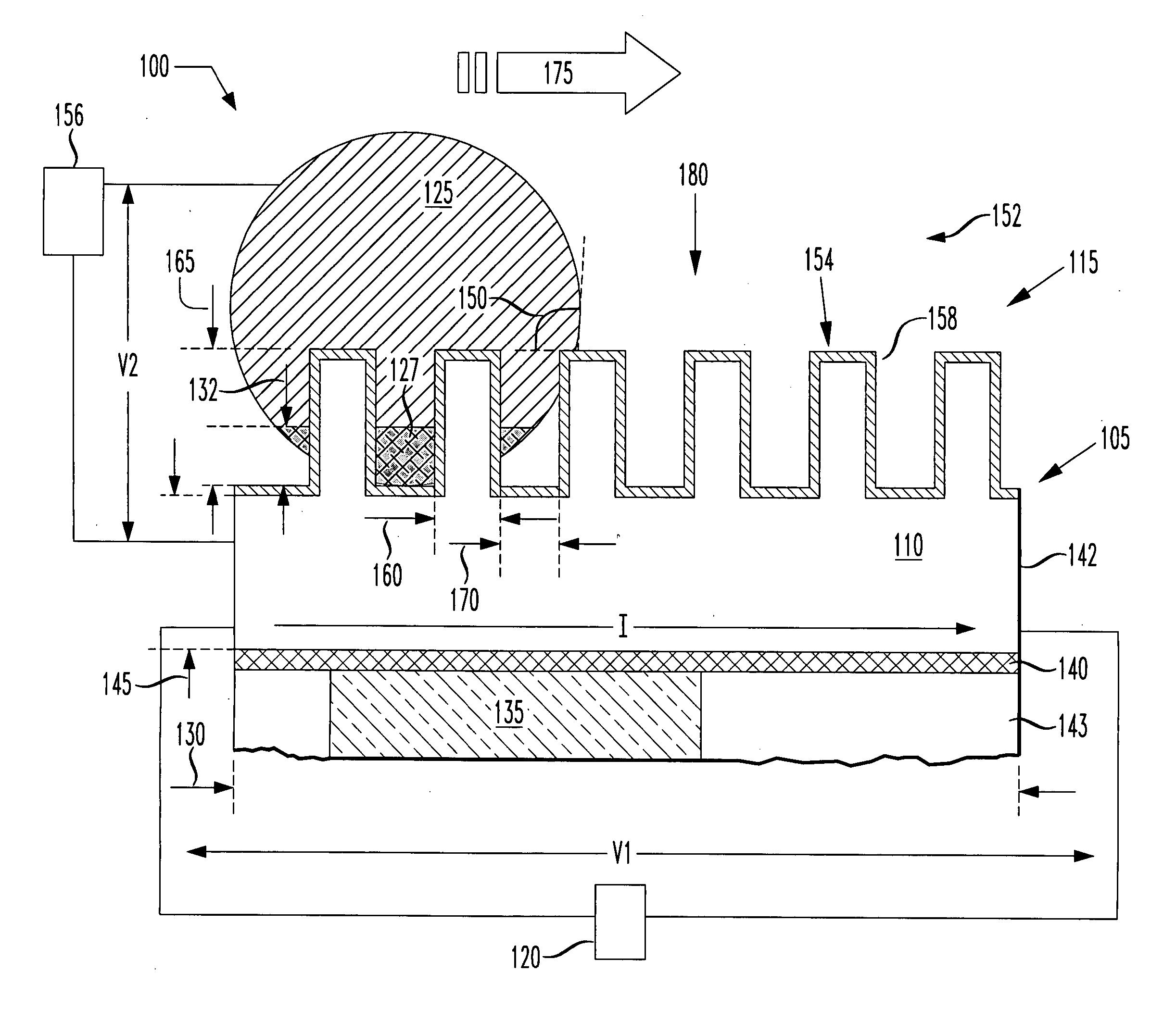
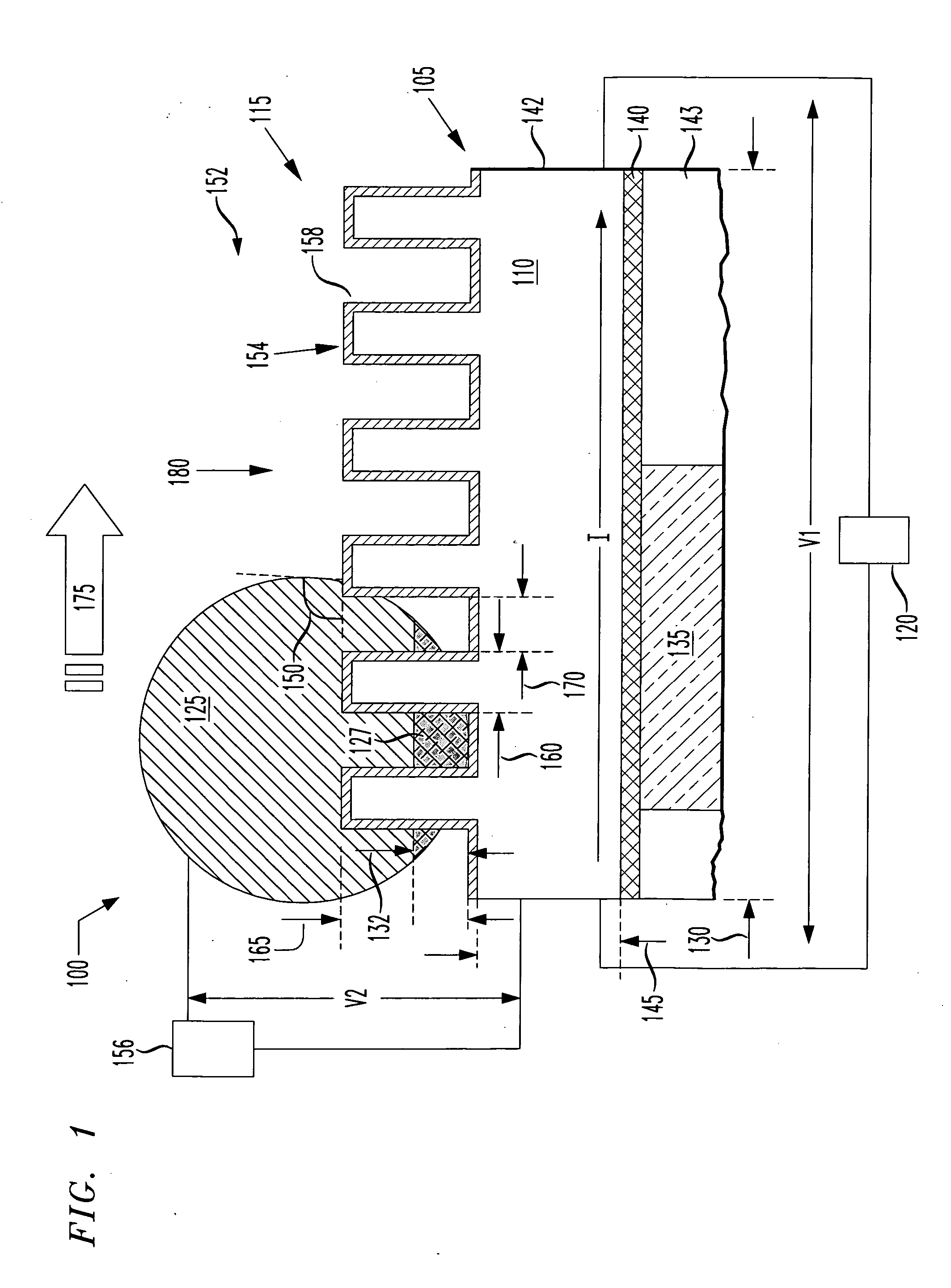
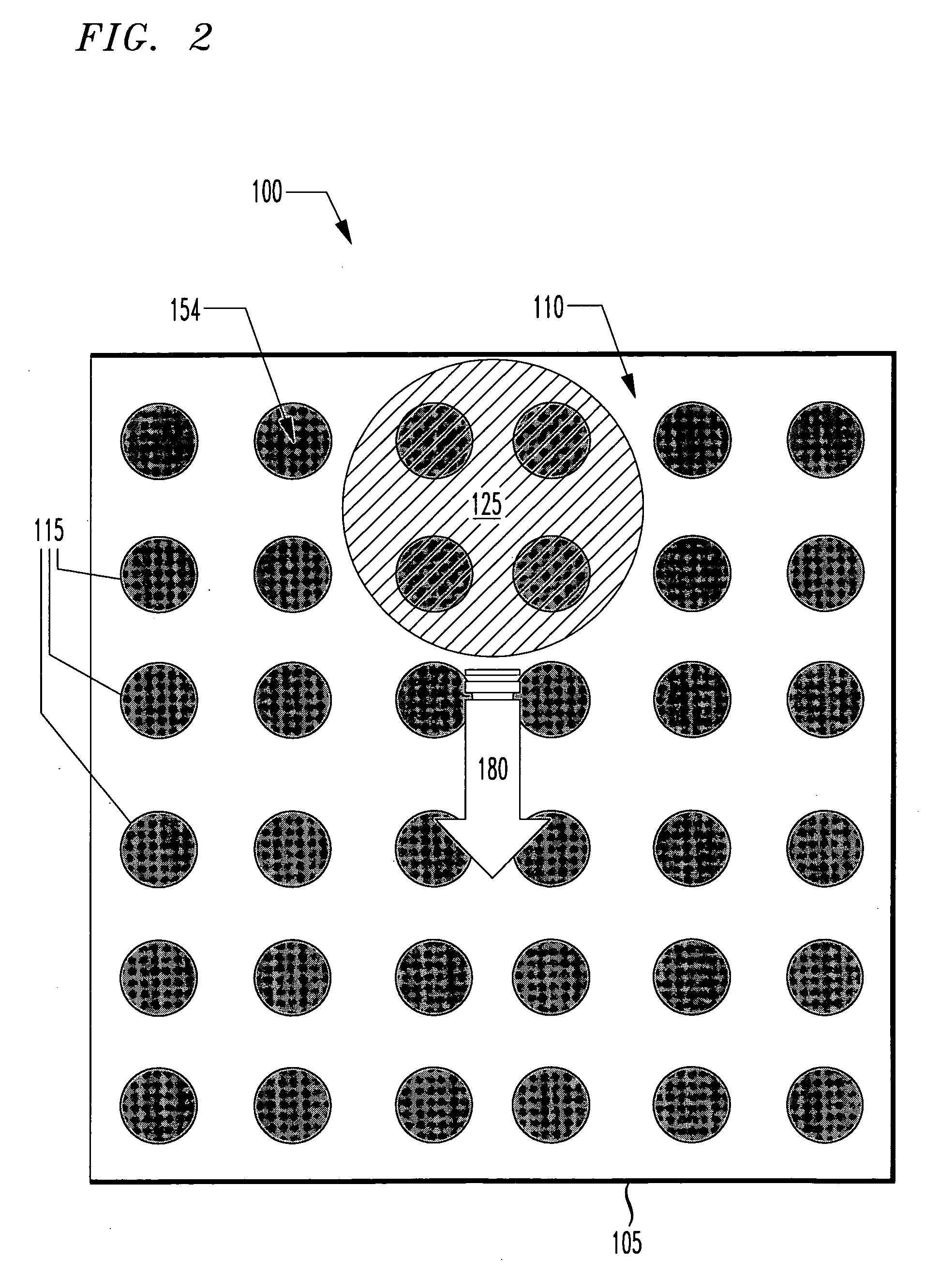
[0016] The present invention recognizes, for the first time, that the vertical position of a fluid can be moved from the bottom to the top of certain kinds of fluid-support-structures by converting a portion of the fluid to a vapor. The application of a current through a conductive base layer that the fluid-support-structures are on causes heating of the lower portion of the fluid. The heated portion of the fluid is rapidly vaporized. The vaporized fluid rapidly expands, thereby pushing the non-vaporized portion of fluid to the tops of the fluid-support-structures.

[0017] As part of the present invention, it was discovered that moving fluids in this manner facilitates the transition of a surface from a wetted to a non-wetted state. It was further discovered that moving fluids in this manner also facilitates the mixing of fluids. For instance, vertically moving two fluids on the surface as described herein can promote convection in the two fluids, resulting in their mixing.

[0018] Ea...


PUM


Abstract

A device comprising a substrate having a base layer, the base layer being connectable to a source of current. The device also includes fluid-support-structures located on the base layer. Each of the fluid-support-structures has at least one dimension of about 1 millimeter or less. The base layer is configured to impart heat to a fluid locatable over the base layer and convert at least a portion of the fluid to a vapor when a current is applied to the base layer.

Description

TECHNICAL FIELD OF THE INVENTION [0001] The present invention is directed, in general, to a device and method for changing the vertical location of a fluid on a structured surface of the device. BACKGROUND OF THE INVENTION [0002] One problem encountered when handling small fluid volumes is to wet and de-wet a surface. Transitioning between a wet and a non-wet surface allows one to control properties of the fluid-solid interface, such as the mobility of a fluid on a surface. Controlling the mobility of a fluid on a surface is advantageous in analytical applications where it is desirable to repeatedly move a fluid to a designated location, immobilize the fluid and remobilize it again. Unfortunately, existing surfaces do not provide adequate reversible control of wetting and de-wetting. [0003] For instance, certain surfaces with raised features, such as posts or pins, may provide so-called superhydrophobic surfaces that strongly inhibit wetting. For example, a droplet of liquid on such...

Claims


Application Information

Patent Timeline
Patent Type & Authority Applications(United States)
IPC IPC(8): B01L3/00
CPCB01F13/0071B01F13/0079B01L3/502792F28F13/185B01L2300/166B01L2300/1827B01L2400/0442B01L2300/089B01F33/3033B01F33/3021
Inventor AIZENBERG, JOANNAHODES, MARC SCOTTKOLODNER, PAUL ROBERTKRUPENKIN, THOMAS NIKITATAYLOR, JOSEPH ASHLEY
Owner ALCATEL LUCENT SAS
Why Eureka
Try Eureka