
Electronics System

Inactive Publication Date: 2007-03-22
VICTOR CO OF JAPAN LTD
View PDF3 Cites 26 Cited by
  • Summary
  • Abstract
  • Description
  • Claims
  • Application Information

AI Technical Summary

Benefits of technology

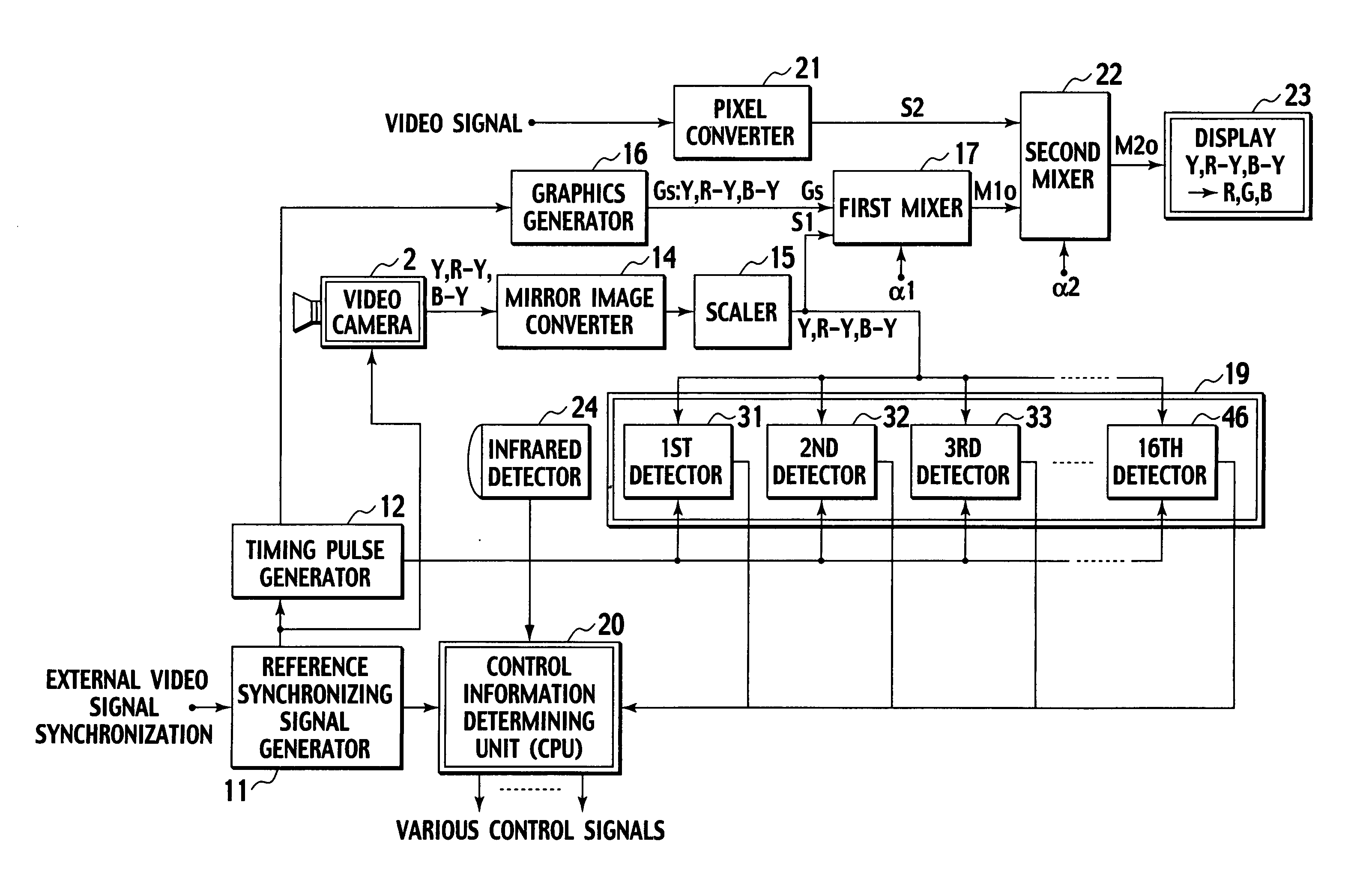
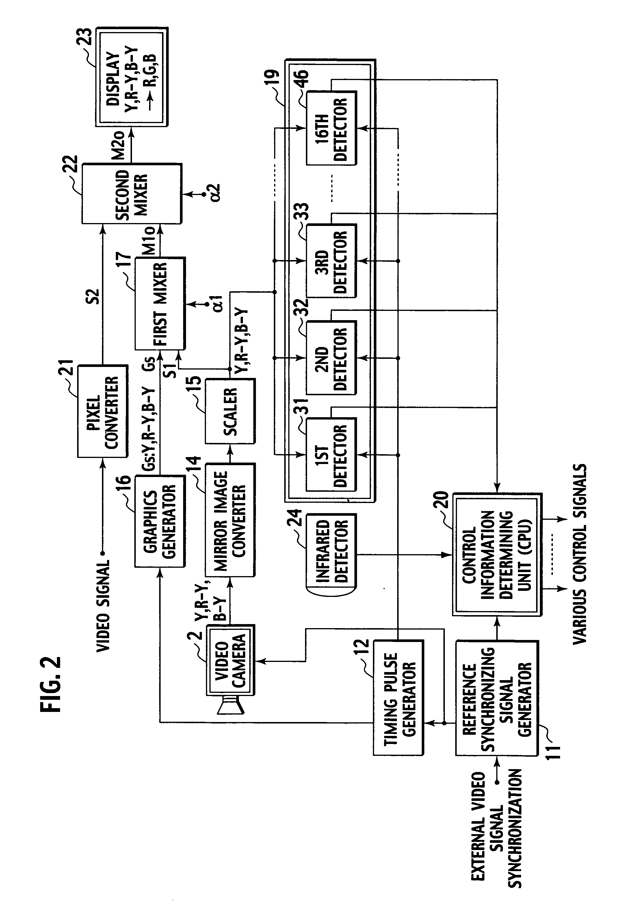
[0012] According to the first aspect, the video camera photographs an operator. The photographed image of the operator is converted into a mirror image. The mirror image is mixed and overlaid with an operational image that contains a control image and a pointing image. The overlaid images are displayed on the display. When the on-hand controller manipulated by the operator and displayed on the display is brought over the pointing image on the display, the display controller detects the same and makes the pointing image follow a movement of the on-hand controller. By moving the on-hand controller, the operator can move the pointing image onto the control image. When the pointing image is brought onto the control image, the detection unit detects that the control image has been specified. Then, a control operation associated with the control image is executed. The first aspect eliminates conventional operation of choosing and pushing one button from among many buttons of a remote controller. The first aspect allows the operator to perform various control operations only by moving the on-hand controller and conducting a single select operation on the on-hand controller.
[0014] The second aspect detects a movement of the on-hand controller according to areas of the image of the on-hand controller in the detection sections divided from the detection frame. The sum total of the areas provided by the detectors, as well as the areas provided by the detectors or a difference between the areas detected in each pair of the detection sections that are positionally symmetrical about the center of the detection frame are used to calculate a motion vector of the image of the on-hand controller. The second aspect can correctly track a movement of the on-hand controller with the pointing image or the control image.
[0018] According to the fourth aspect, the video camera photographs an operator. The photographed image of the operator is converted into a mirror image. The mirror image is mixed and overlaid with an operational image that contains a control image. The overlaid images are displayed on the display. When the on-hand controller manipulated by the operator and displayed on the display is brought over the control image on the display, the display controller detects the same and makes the control image follow a movement of the on-hand controller. Accordingly, the operator can move the control image to a required position on the display and create an optional operational image. In this way, the fourth aspect enables a continuously moving operation for controlling, for example, the volume.

Problems solved by technology

In this way, operation of the remote controller on the EPG is complicated and inconvenient like the operation on data broadcasting.
This controller, therefore, is inconvenient for a person who is unfamiliar with the operation of a personal computer.
From the view point of information literacy (ability of utilizing information), the related art is somewhat unreasonable because it forcibly introduces the handling scheme of personal computers into the handling scheme of home appliances such as television sets.
In this regard, present remote controllers attached to home appliances are insufficient.
To serve as pointing devices, the conventional remote controllers are not user-friendly.
What is problematic is the user must find a correct one among the remote controllers when controlling one of the networked devices.
In addition, the conventional remote controllers are poor at handling a variety of information pieces provided by web sites on the Internet.

Method used


Image

  • Electronics System
  • Electronics System
  • Electronics System

Examples


Embodiment Construction

[0056] Electronics systems according to embodiments of the present invention will be explained with reference to the drawings.

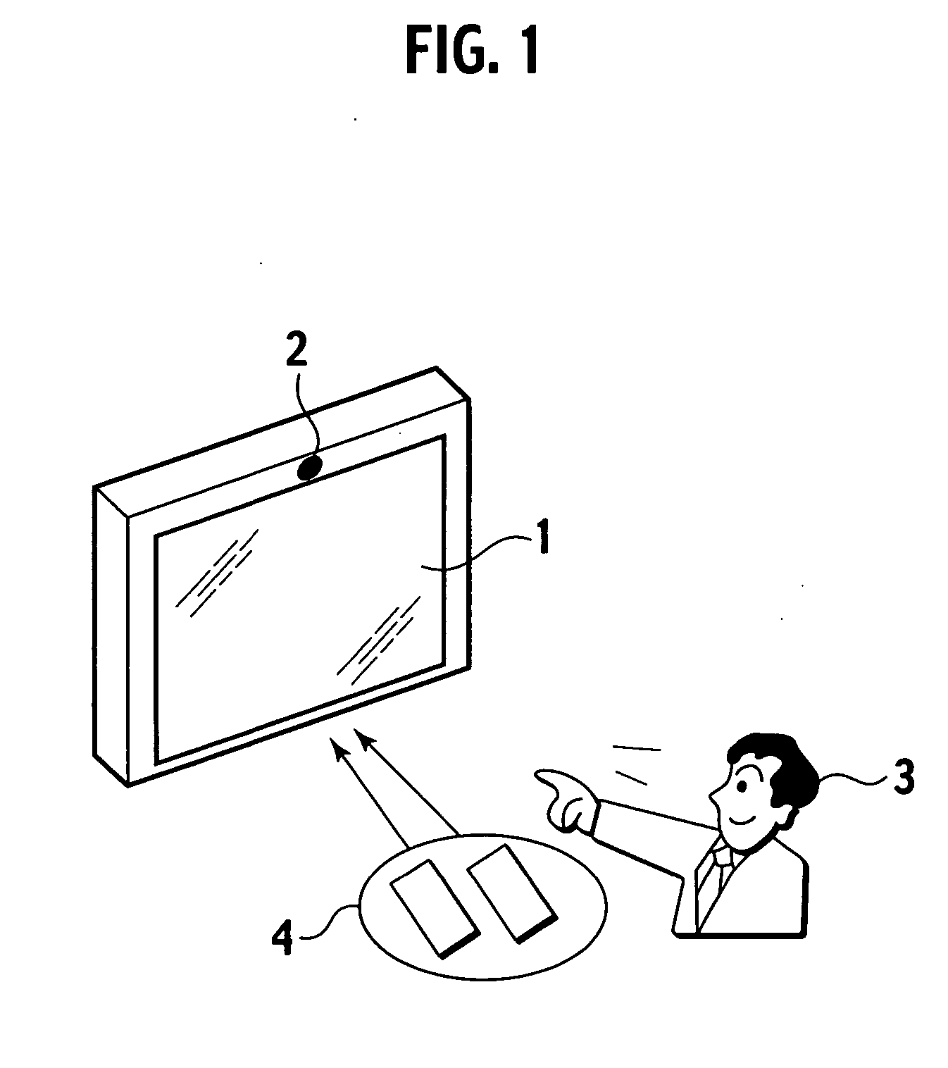
[0057]FIG. 1 shows the difference between an operation using a remote controller according to a related art and an operation according to the present invention. A user (operator) 3 operates a television set 1 . According to the related art, the user 3 must hold the remote controller 4, direct the remote controller 4 toward the television set 1 , and push a key of required function on the remote controller 4. If the television set 1 has many peripheral devices, there will be many remote controllers and the user must find a proper one from among the many remote controllers. This is inconvenient for the user 3.

[0058] On the other hand, the present invention provides the television set 1 with a video camera 2. The video camera 2 photographs the user 3. From the image provided by the video camera 2, an operation conducted by the user 3 is recognized and a contro...


PUM


Abstract

An electronics system includes an electronic appliance with a display, a video camera for photographing an operator, and a universal remote controller for remotely controlling the electronic appliance. The image of the operator photographed with the video camera is converted into a mirror image. The mirror image of the operator is overlapped with an operational image which includes control icons and a pointer, and the overlapped images are displayed on the display. The operator manipulates a button on the universal remote controller, and the universal remote controller emits light. The light is detected by a detection unit of the electronics system. When the light is brought on to the pointer, the pointer starts to follow a movement of the universal remote controller manipulated by the operator. The operator moves the pointer onto a required one of the control icons and operates the button of the universal remote controller, to execute a control operation associated with the control icon.

Description

BACKGROUND OF THE INVENTION [0001] 1. Field of the Invention [0002] The present invention relates to an electronics system, and particularly, to an electronic system for remotely controlling an electronic appliance having a display, such as a television set and a personal computer. [0003] 2. Description of Related Art [0004] In the 1980s, infrared remote controllers started to be attached to home appliances such as television sets. The remote control user interfaces have widely spread and greatly changed the usage of home appliances. At present, the operation with remote controllers is in the mainstream. The remote controller basically employs a one-push, one-function operation. A television remote controller, for example, has ON / OFF, CHANNEL, VOLUME, and INPUT SELECT keys for conducting respective functions. The remote controllers are very useful for remotely controlling the television set and electronic devices connected to the television set. [0005] Data broadcasting that has sta...

Claims


Application Information

Patent Timeline
IPC IPC(8): H04N5/222G06F3/033G06F3/0346G06F3/038H04N5/00
CPCG06F3/011G06F3/0346G06F3/0304
Inventor KITAURA, MASAHIRO
Owner VICTOR CO OF JAPAN LTD
Learn More