Controller for electronic appliance

a technology for controlling devices and electronic appliances, applied in the direction of selective content distribution, television systems, instruments, etc., can solve the problems of troublesome user operation, troublesome user, and user trouble, and achieve the effect of flexible remote control

Active Publication Date: 2006-03-23
JVC KENWOOD CORP A CORP OF JAPAN
View PDF11 Cites 22 Cited by
  • Summary
  • Abstract
  • Description
  • Claims
  • Application Information

AI Technical Summary

Benefits of technology

[0010] In view of the above-mentioned problems, an object of the present invention is to provide a controller capable of flexibly conducting remote control on a variety of electronic appliances without a remote controlling device manipulated in the hands of a user.

Problems solved by technology

This is troublesome for the user.
This is also troublesome for the user.
If the user is unfamiliar with a personal computer, such pointing operation is troublesome for the user.
Applying the operation techniques of personal computers to home appliances is unreasonable in view of information literacy (ability to use information).
Such a variety of information pieces involve a variety of handling methods, and current remote controllers accompanying home appliances are insufficient to cope with such a variety of handling methods.
The conventional remote controller, however, is problematic to use it as a pointing device.
This problem is frequently experienced in present days when a television receiver, for example, is connected to other devices such as a VTR, a video disk, and an audio unit.
It is bothersome for the user to find a correct one among the remote controllers of these interlinked devices.
In addition, the conventional remote controller is substantially unable to select and control information pieces provided by various web sites via the Internet.

Method used


Image

  • Controller for electronic appliance
  • Controller for electronic appliance
  • Controller for electronic appliance

Examples


Embodiment Construction

[0064] An embodiment of the present invention will be explained with reference to the accompanying drawings.

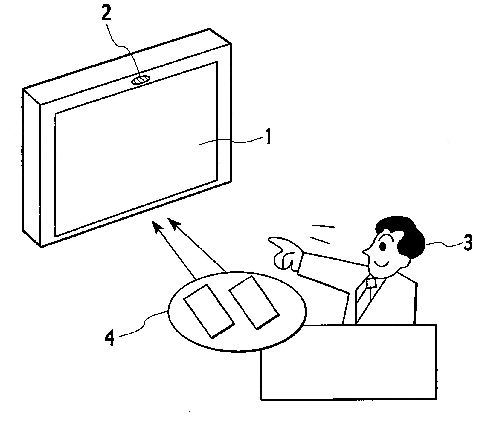
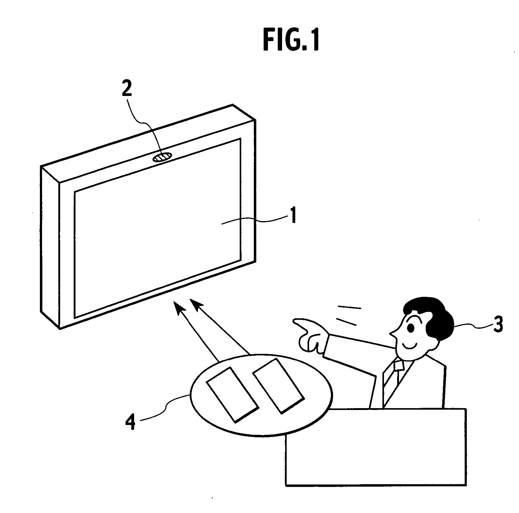
[0065]FIG. 1 shows the difference between an operation using a remote controller according to a related art and an operation according to the present invention. Viewer (user) 3 operates a television receiver 1. According to the related art, the user 3 must hold the remote controller 4, direct the remote controller 4 toward the television receiver 1, and push a key of required function on the remote controller 4. Without the remote controller 4, the user 3 cannot operate the television receiver 1, and therefore, must frequently experience inconvenience.

[0066] On the other hand, the present invention provides the television receiver 1 with a video camera 2. The video camera 2 photographs the user 3. From the image provided by the video camera 2, an operation conducted by the user 3 is recognized and an operation corresponding to the recognized operation is carried out with res...


PUM


Abstract

A controller controls an electronic appliance. The electronic appliance has a display. The controller employs a video camera to photograph an image of a user and converts the image into a mirror image. The controller generates an operational image including operation buttons, overlays the operational image on the user's image, and displays the images on the display. In the displayed images, the user moves his or her hand onto one of the displayed operation buttons and bends the fingers of the hand to select the operation button. This selecting operation is detected by a detector of the controller, and information about the selected operation button is supplied to a processing unit, which outputs control signals corresponding to the selected operation button.

Description

BACKGROUND OF THE INVENTION [0001] 1. Field of the Invention [0002] The present invention relates to a controller for an electronic appliance, and particularly, to a controller for remotely controlling an electronic appliance having a display, such as a television receiver and a personal computer. [0003] 2. Description of Related Art [0004] In the 1980s, home appliances such as television receivers started to have infrared remote controllers. Remote-control user interfaces have widely spread and greatly changed the style of use of home appliances. At present, the remote control is in the main stream. The remote controllers basically employ the same scheme when accomplishing functions. Namely, they require a user to push a key corresponding to a desired function. For example, a remote controller for a television receiver has keys “Power,”“Channel,”“Volume,”“Input switching,” and the like to realize convenient remote control of the television receiver. [0005] To control data broadcast...

Claims


Application Information

Patent Timeline
Patent Type & Authority Applications(United States)
IPC IPC(8): G09G5/00G06F3/01G06F3/038G06F3/0482G06F3/0487G06F13/00H04N5/44H04Q9/00
CPCG06F3/011H04N5/44582H04N21/4316H04N21/4223H04N21/44218H04N21/4318H04N21/44008H04N21/4402H04N21/4312H04N21/47H04N21/42204
Inventor KITAURA, MASAHIRO
Owner JVC KENWOOD CORP A CORP OF JAPAN
Why Eureka
Try Eureka