Method and system for mortar removal

a mortar and mortar technology, applied in adaptive control, computer control, instruments, etc., can solve the problems of silica dust generation in the process of removing deteriorated mortar from the masonry joints, high cost of current repointing methods, and labor intensive and time-consuming, so as to promote worker safety, time-consuming, and labor-intensive effects

Active Publication Date: 2013-09-03
SKY CLIMBER FIELD SERVICES
View PDF18 Cites 6 Cited by
  • Summary
  • Abstract
  • Description
  • Claims
  • Application Information

AI Technical Summary

Benefits of technology

[0014]In one embodiment, the method may further include the step of brushing at least a portion of one of the plurality of joints along the work path after mortar has been removed. This step helps to properly prepare the joints so that they may filled in with new mortar. In yet another embodiment, the method for mortar removal may include the step of blowing air into at least a portion of one of the plurality of joints along the work path after mortar has been removed. Preferably this step follows the step of brushing the plurality of joints. Blowing air into the joints further prepares the joints so that they may be filled in with new mortar.
[0015]The presently disclosed method and system for mortar removal provides an alternative to the prior art methods that are labor intensive and time consuming. The presently disclosed method and system for mortar removal also promotes worker safety by containing contaminants and eliminating the risk of a worker developing carpal tunnel syndrome caused by grinding the mortar by hand. Further, the method and system for mortar removal will reduce injuries caused by the prior art hand tools utilized to remove mortar from joints.

Problems solved by technology

Such methods are very labor intensive and time consuming, which makes the current repointing methods very expensive.
In addition, the process of removing the deteriorated mortar from the masonry joints generates silica dust.
Masonry workers who inhale silica dust run the risk of developing silicosis, a disabling and many times fatal disease that affects the lungs.

Method used


Image

  • Method and system for mortar removal
  • Method and system for mortar removal
  • Method and system for mortar removal

Examples


Embodiment Construction

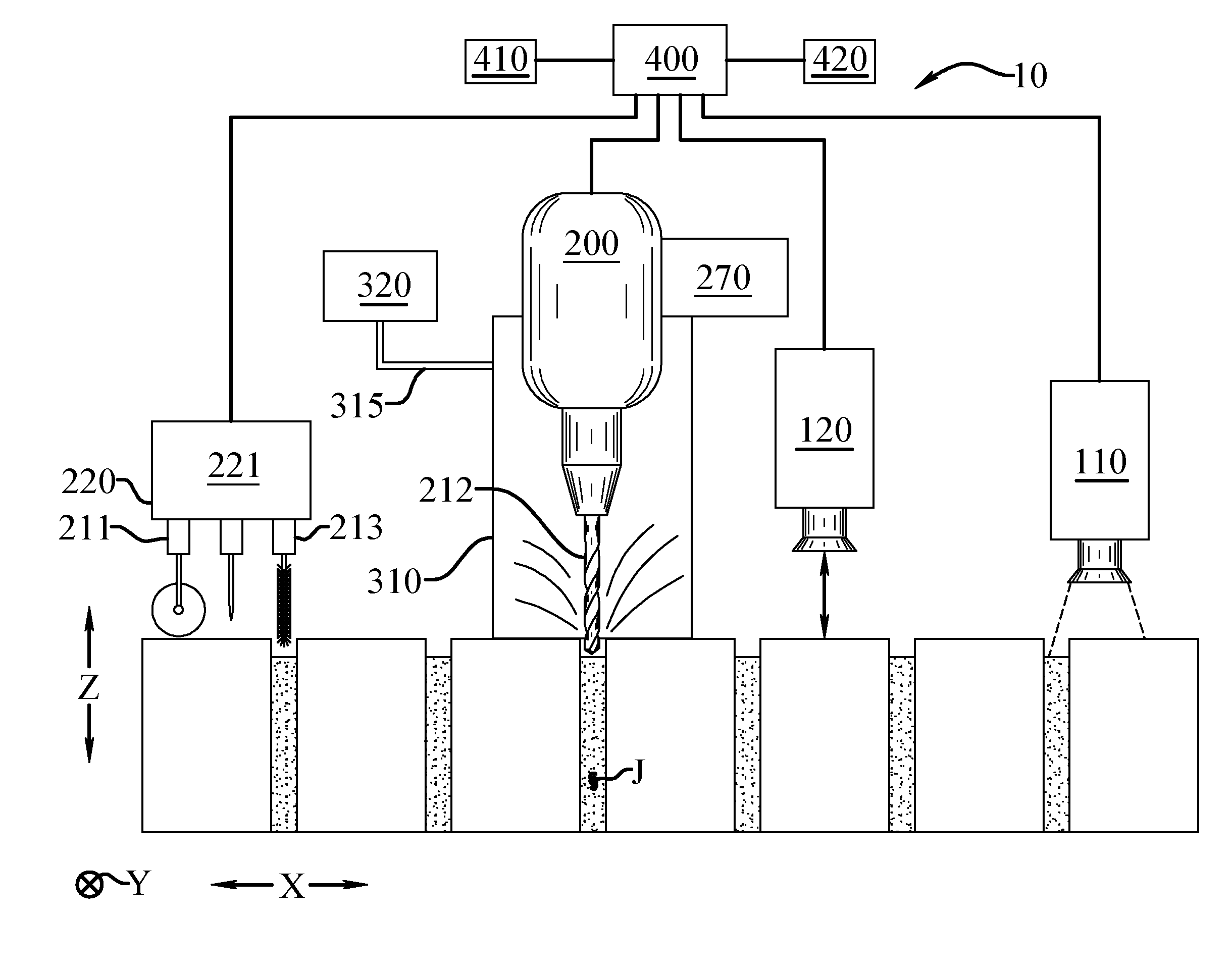
[0028]The presently disclosed method and system (10) for mortar removal enables a significant advance in the state of the art. The preferred embodiments of the method and system (10) accomplish this by new and novel arrangements of elements and methods that are configured in unique and novel ways and which demonstrate previously unavailable but preferred and desirable capabilities. The description set forth below in connection with the drawings is intended merely as a description of the embodiments of the claimed method and system (10), and is not intended to represent the only form in which the method and system (10) may be constructed or utilized. The description sets forth the designs, functions, means, and methods of implementing the method and system (10) in connection with the illustrated embodiments. It is to be understood, however, that the same or equivalent functions and features may be accomplished by different embodiments that are also intended to be encompassed within t...


PUM


Abstract

A method and system for removing mortar from a plurality of joints between a plurality of masonry units in a masonry structure is provided. The steps for accomplishing the method include sensing the location of at least one of the plurality of joints between the plurality of masonry units and transmitting joint location data to a computer control system. Next, the computer control system computes a work path based upon the joint location data. In a further step, the computer control system controls the position and operation of at least one work tool such that the work tool moves along the work path to remove mortar from a portion of one of the plurality of joints along the work path. Finally, the dust and debris generated when the work tool removes mortar from a portion of one of the plurality of joints along the work path is contained and removed.

Description

CROSS-REFERENCE TO RELATED APPLICATIONS[0001]Not applicable.STATEMENT REGARDING FEDERALLY SPONSORED RESEARCH OR DEVELOPMENT[0002]Not applicable.TECHNICAL FIELD[0003]The present disclosure relates to the field of masonry and masonry restoration, and more particularly, to a method and system for removing mortar from a plurality of joints between a plurality of masonry units in a masonry structure.BACKGROUND OF THE INVENTION[0004]Over time, every masonry structure will require the mortar between masonry joints to be removed and replaced with new mortar. The mortar between masonry joints is very important for a number of reasons. For example, the mortar provides the strength to hold the masonry units together; it serves as a type of cushion between masonry units; and it provides a water-resistant barrier to help prevent moisture and other contaminants from entering the structure. Thus, when the mortar begins to show signs of deterioration, it must be removed and replaced with new mortar...

Claims


Application Information

Patent Timeline
Patent Type & Authority Patents(United States)
IPC IPC(8): G05D7/00G05D11/00F15B19/00F16K37/00G05D7/06
CPCB25J9/1679G05D7/0635G05B15/02F15B19/005F16K37/0075G05D7/0664G05D7/0688
Inventor WEINHARDT, EDANASLS, GEORGE
Owner SKY CLIMBER FIELD SERVICES
Why Eureka
Try Eureka