Tamper monitor circuit

a monitor circuit and monitoring circuit technology, applied in the field of tamper monitoring, can solve the problems of monitor circuits that emit false tamper alarms, circuits suffer certain drawbacks, and compromise the security of devices,

Active Publication Date: 2007-03-29
HARRIS CORP
View PDF11 Cites 71 Cited by
  • Summary
  • Abstract
  • Description
  • Claims
  • Application Information

AI Technical Summary

Benefits of technology

[0006] The present invention provides a tamper monitor circuit that detects voltage, temperature, and/or clock variations that may be associated with a circuit tampering technique, and triggers an appropriate tamper response. In one embodiment, and by way of example only, a tamper monitor circuit includes a reference oscillator, a detection oscillator, and a comparison circuit. The reference oscillator is operable to supply a reference signal having a reference frequency. The detection oscillator is configured to operate at a circuit temperature and to be energized with a su...

Problems solved by technology

As is generally known, varying one or more of these parameters can cause the device to transfer into an unanticipated operational mode or state, which may compromise the security of the device.
Although present monitor circuits do provide a level of tamper monitoring and protection, these circuits also suffer certain drawbacks.
Moreover, some monitor circuits undesir...

Method used


Image

  • Tamper monitor circuit
  • Tamper monitor circuit
  • Tamper monitor circuit

Examples


Embodiment Construction

[0014] The following detailed description of the invention is merely exemplary in nature and is not intended to limit the invention or the application and uses of the invention. Furthermore, there is no intention to be bound by any theory presented in the preceding background of the invention or the following detailed description of the invention.

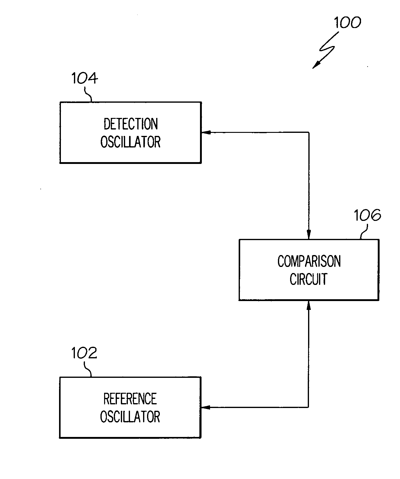
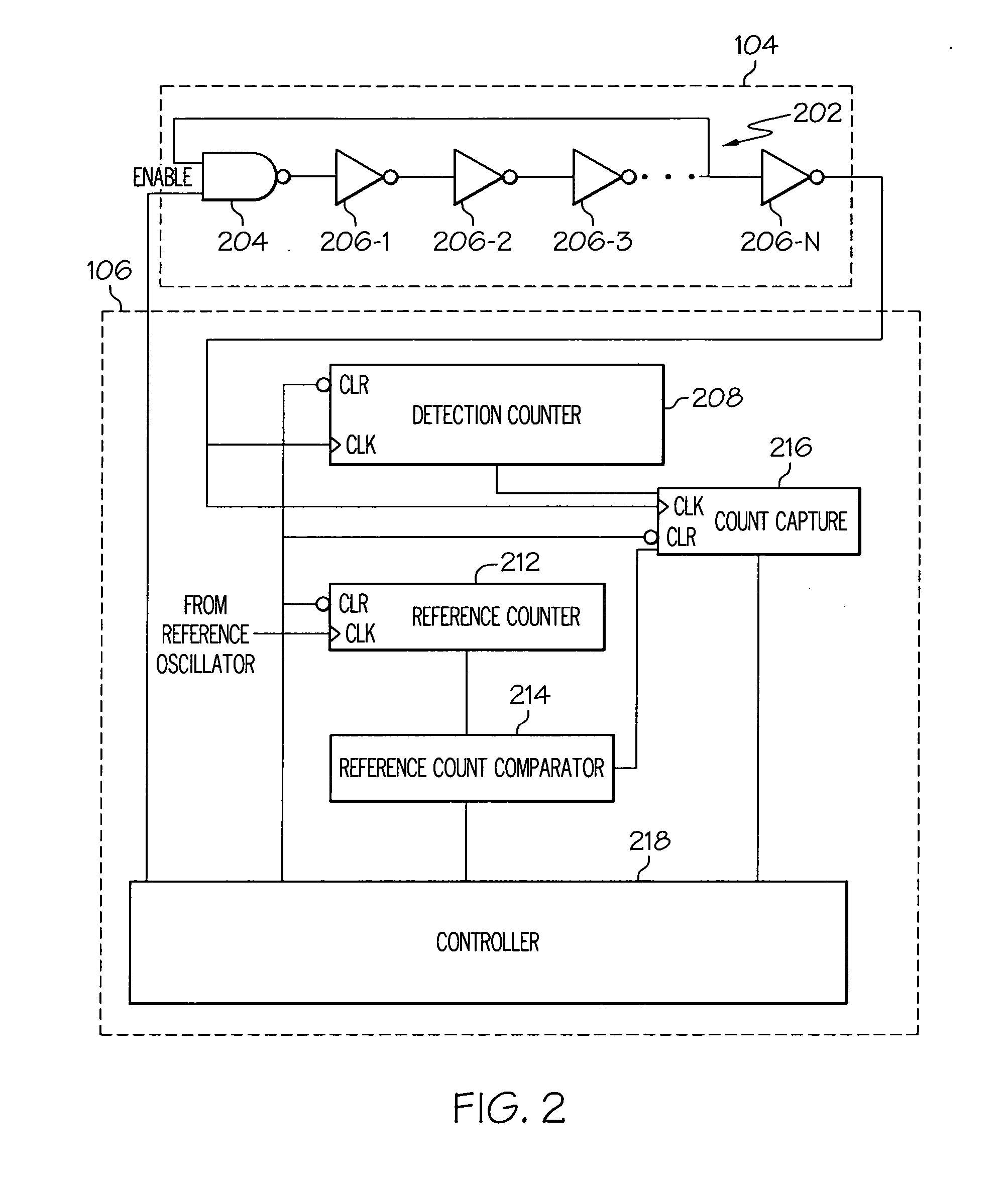
[0015] A functional block diagram of an exemplary monitor circuit 100 is depicted in FIG. 1 and includes a reference oscillator 102, a detection oscillator 104, and a comparison circuit 106. The circuits 102-106 that comprise the monitor circuit 100 each operate at the same or different circuit temperature, and are each energized with a supply voltage that is supplied from one or more non-illustrated power supplies. For example, the reference oscillator 102, the detection oscillator 104, and the comparison circuit 106 could all be energized from the same power supply, or one or more of the circuits 102-106 could be energized from separate ...


PUM


Abstract

A tamper monitor circuit detects voltage, temperature, and/or clock variations that may be associated with a circuit tampering technique, and triggers an appropriate tamper response. The tamper monitor circuit includes a reference oscillator, a detection oscillator, and a comparison circuit. The reference oscillator supplies a reference signal having a reference frequency. The detection oscillator operates at a circuit temperature and is energized with a supply voltage, and supplies a detection signal having a frequency that varies with variations in the circuit temperature, variations in the supply voltage, or both. The comparison circuit receives the reference signal and the detection signal and, in response to the reference signal, selectively determines the frequency of the detection signal, determines a frequency difference between two or more of the determined frequencies, and supplies a tamper detect signal if the determined frequency difference exceeds a predetermined difference threshold.

Description

TECHNICAL FIELD [0001] The present invention generally relates to tamper monitoring and, more particularly, to a tamper monitoring circuit that accurately detects tampering actions that result in or from temperature, voltage, and / or reference clock variances. BACKGROUND [0002] Microcontrollers and various other embedded circuit devices are used in, or used as, secure electronic devices that perform various types of secure transactions, and to store various types of secure data. For example, secure electronic devices are more and more being used to conduct secure currency transfers, secure information transfers, and secure data storage operations. As a result of the increased usage of microcontrollers, and similar circuit devices, for storing and transferring secure information and data, there has also been an increase in the number of people dedicated to, and the number of techniques developed for, reverse engineering secure electronic devices. [0003] Various non-destructive reverse...

Claims


Application Information

Patent Timeline
IPC IPC(8): B60Q1/00
CPCG06F21/75G06F21/554
Inventor DOI, BRYAN C.
Owner HARRIS CORP
Why Eureka
Try Eureka