
Retraction mechanism of light pen

a light pen and retracting mechanism technology, applied in the field of retracting mechanisms of light pen, can solve the problems of light pen disengagement with its receiving receptacle, ejection device may have elastic fatigue problem, prior art suffered from a couple of disadvantages

Inactive Publication Date: 2007-04-05
HWA YING INDAL
View PDF4 Cites 31 Cited by
  • Summary
  • Abstract
  • Description
  • Claims
  • Application Information

AI Technical Summary

Benefits of technology

[0008] It is therefore an object of the present invention to provide a light pen comprising a barrel comprising internal threads at a lower portion; a writing head comprising a hollow nose including internal threads formed on an upper portion of its inner surface, and a cylindrical head; an elastic ejection assembly provided inside a lower portion of the barrel and an upper portion of the writing head and comprising an elongate pilot bar including annular first teeth, a first spring provided in the nose and biased between a bottom of the pilot bar and a shoulder of the head, a pushing cylinder including a plurality of second teeth around its lower portion, and a lower recess for receiving an upper extension of the pilot bar; and a hollow cylindrical member including lower external threads secured to both the internal threads of the writing head and the internal threads of the barrel, a plurality of longitudinal first grooves around its inner surface, and a plurality of longitudinal second grooves alternate with the first grooves; and a plunger comprising a lower hollow cylinder including inner threads around its inner surface, and at least one annular protruded seal proximate a bottom of the cylinder, and a pushing rod including an enlarged head and lower outer threads wherein the cylinder passes the barrel to cause the inner threads of the plunger to secure to the outer threads of the plunger, and the seal is stopped by an inwardly extending rim on a top of the barrel when the cylinder passes the barrel for preventing the cylinder from disengaging with the barrel; whereby in a retracting operation of the light pen, pressing the pushing rod into the barrel will move the pushing cylinder to compress the first spring, push the first teeth out of the first grooves, clockwise turn the first teeth to move from the first groove to the adjacent second groove, and cause the pilot bar to jump a pitch to completely conceal the light pen in a receptacle of an electronic device; and in an extending operation of the light pen, pressing the pushing rod again will clockwise turn the first teeth to move from the second groove to the adjacent first groove to cause the pilot bar to jump another pitch, and release a stored elastic force of the first spring to push the pushing rod partially out of the receptacle.

Problems solved by technology

However, the prior art suffered from a couple of disadvantages.
For example, the ejection device may have an elastic fatigue problem after a relatively long period time of use.
Further, the light pen may disengage with its receiving receptacle when a person touches the light pen unintentionally.

Method used


Image

  • Retraction mechanism of light pen
  • Retraction mechanism of light pen
  • Retraction mechanism of light pen

Examples


Embodiment Construction

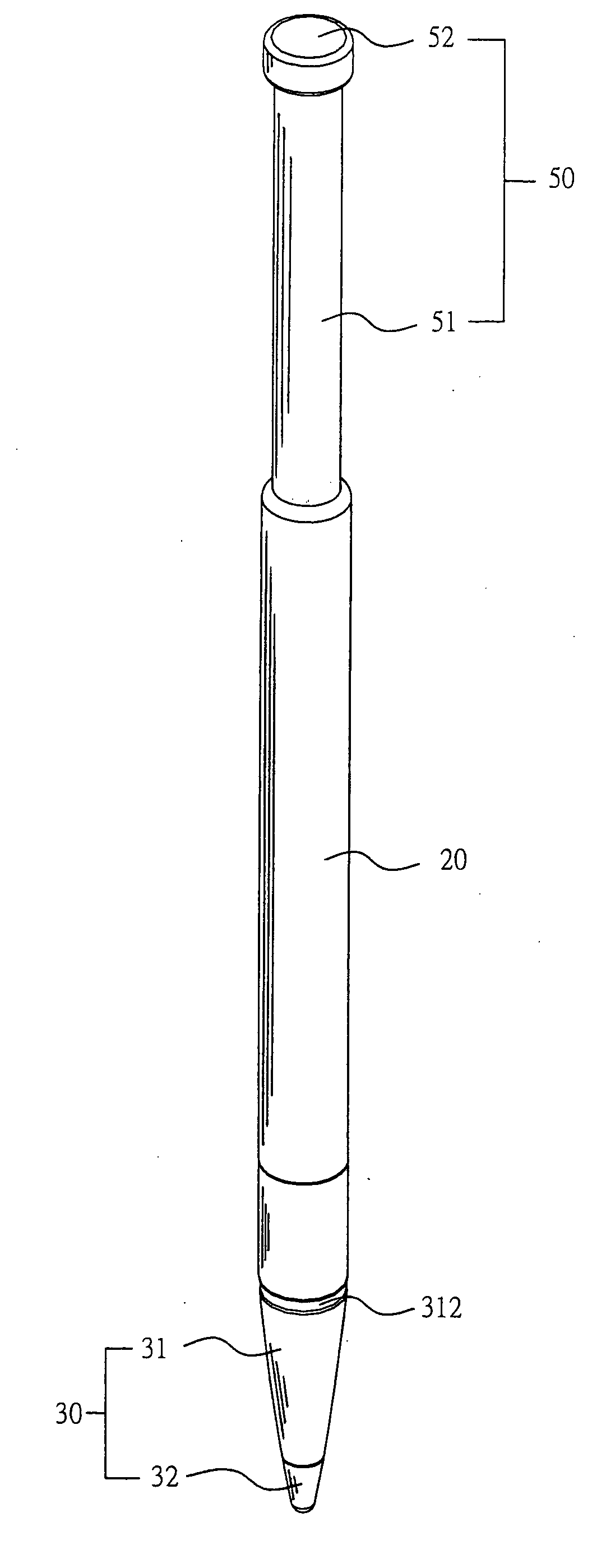
[0021] Referring to FIGS. 4 to 12, a light pen having an ejection mechanism in accordance with a preferred embodiment of the invention is shown. The light pen comprises a writing head 30, a barrel 20, an elastic ejection assembly 40, and a plunger 50. Each component is discussed in detailed below.

[0022] The barrel 20 comprises internal threads 21 at a lower portion. The writing head 30 comprises a nose 31 including an axial bore 311, internal threads 313 formed on an upper portion of its inner surface, and an annular groove 312 at a joining portion of its hollow, cylindrical upper portion and its conic lower portion; and a cylindrical head 32. The elastic ejection assembly 40 is provided inside a lower portion of the barrel 20 and an upper portion of the writing head 30 and comprises an elongate pilot bar 41 including a tooth section 411 therearound, the tooth section 411 having three teeth 412 equally spaced therearound; a spring 44 provided in the bore 311 and biased between a bo...


PUM


Abstract

Provided is a light pen comprising an elastic ejection assembly. In a retracting operation of the light pen, pressing a pushing rod into a barrel will move a pushing cylinder to compress a spring, push first teeth out of first grooves, clockwise turn the first teeth to move from the first groove to adjacent second groove, and cause a pilot bar to jump a pitch to completely conceal the light pen in a receptacle of an electronic device In an extending operation of the light pen, pressing the pushing rod again will clockwise turn the first teeth to move from the second groove to the adjacent first groove to cause the pilot bar to jump another pitch, and release a stored elastic force of the spring to push the pushing rod partially out of the receptacle.

Description

BACKGROUND OF THE INVENTION [0001] 1. Field of Invention [0002] The present invention relates to light pens and more particularly to a retraction mechanism of light pen with improved characteristics. [0003] 2. Related Art [0004] A conventional PDA (personal digital assistant) 200 is shown in FIG. 1. A light pen 300 is adapted to touch an LCD (liquid crystal display) 400 in operation. Conventionally, a deep receptacle 210 is formed in the PDA 200 for receiving head of the light pen 300. Such arrangement is not desirable since the light pen 300 tends to disengage with the receptacle 210. [0005] Another device having a prior ejection mechanism for a light pen is shown in FIG. 2. The mechanism is provided along one side of the device and comprises a deep receptacle for receiving a portion of the light pen, an elastic ejection device provided at bottom of the receptacle, the ejection device being adapted to be pressed by the head of the inserted light pen such that a further pressing of ...

Claims


Application Information

Patent Timeline
Patent Type & Authority Applications(United States)
IPC IPC(8): G09G5/00
CPCG06F1/1626G06F3/03545G06F2200/1632
Inventor LIU, JUNG TSAN
Owner HWA YING INDAL
Learn More