Shooting range simulator system and method

a simulator and shooting range technology, applied in the field of shooting range simulators, can solve the problems of not being able to distinguish between multiple aiming devices aiming at the same position, not being able to detect where an aiming device is, and being unable to detect the difference between the aiming location and the actual hit position

Inactive Publication Date: 2007-04-05
ELBIT SYST LTD
View PDF10 Cites 21 Cited by
  • Summary
  • Abstract
  • Description
  • Claims
  • Application Information

AI Technical Summary

Benefits of technology

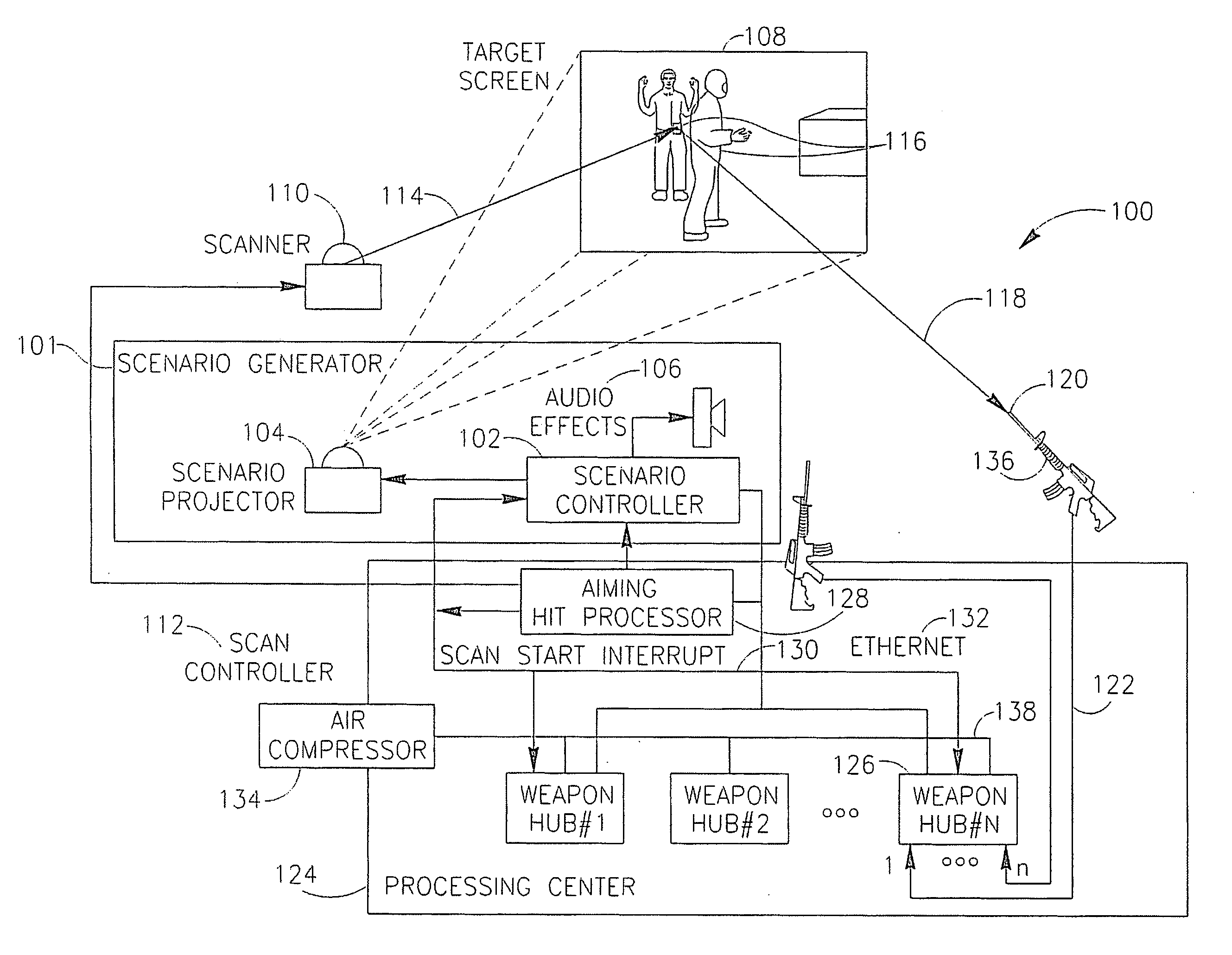
[0016] According to some exemplary embodiments of the invention, the shooting range simulator system may include an event signal generator to simulate additional aspects of a shooting range, e.g. “firing” of a simulated weapon. According to some exemplary embodiments of the invention, a trigger depression event signal, for example, may be generated and transmitted to the processing center in response to mechanical actions of a shooter. For example, the shooter may depress a trigger of a simulated weapon to activate a micro-switch and generate an electric signal. Further, the simulated weapon trigger may, for example, be connected to an air compressor, which may be able to physically simulate a kick-back effect.

Problems solved by technology

Additionally, there is typically a discrepancy between an aimed-at location and actual hit positions.
Such a system may not be able to distinguish between multiple aiming devices aiming at the same position on the target screen.
Such a system may not be able to detect where an aiming device is aimed on the target screen unless it is perfectly aimed at the particular target, and thus may not be able to monitor misses or aiming in general, and will give a hit / miss indication only.
Generally, existing shooting range simulator systems and methods may rely heavily on image-processing, may be costly in resources, and may be inefficient for tracking multiple aiming devices randomly firing at the same target screen.

Method used


Image

  • Shooting range simulator system and method
  • Shooting range simulator system and method
  • Shooting range simulator system and method

Examples


Embodiment Construction

[0028] In the following detailed description, numerous specific details are set forth in order to provide a thorough understanding of the invention. However, it will be understood by those of ordinary skill in the art that the present invention may be practiced without these specific details. In other instances, well-known methods, procedures, components and circuits may not have been described in detail so as not to obscure the present invention.

[0029] Unless specifically stated otherwise, as apparent from the following discussions, it is appreciated that throughout the specification discussions utilizing terms such as “processing,”“computing,”“calculating,”“determining,” or the like, refer to the action and / or processes of a computer or computing system, or similar electronic computing device, that manipulate and / or transform data represented as physical, such as electronic, quantities within the computing system's registers and / or memories into other data similarly represented a...


PUM


Abstract

Embodiments of the present invention provide a shooting range simulator system and method able to monitor the aiming history of a shooter. The method may include determining an aimed-at position of one or more aiming devices on a target screen by selectively illuminating positions on the screen according to a predefined scheme; detecting scattered light from the illuminated position from one or more viewing angles; and deriving coordinates of the aimed-at position based on the timing of the detection relative to the scanning scheme. The system may include a scanner to selectively illuminate screen elements and a processing center to determine an aimed-at position on the screen. Additional features are described and claimed.

Description

CROSS REFERENCE TO RELATED APPLICATIONS [0001] This application claims the benefit of Israeli application Serial No. 171263, filed on Oct. 3, 2005 and entitled “SHOOTING RANGE SIMULATOR SYSTEM AND METHOD”, which is incorporated in its entirety herein by reference. FIELD OF THE INVENTION [0002] The invention relates to the field of shooting range simulators and, more particularly, to systems and methods of aim detection and hit detection. BACKGROUND OF THE INVENTION [0003] Conventional, physical, shooting ranges allow a person (“shooter”) to improve their skills, especially with regards to aiming, with a firearm-type weapon though repeated practice in controlled conditions. A virtual shooting range, with the benefit of computer-simulations and other techological advancements, may have the further advantage of being able to provide sophisticated feedback for training purposes. For example, in some shooting range simulators, it may be possible to discern, not just whether a shooter hit...

Claims


Application Information

Patent Timeline
Patent Type & Authority Applications(United States)
IPC IPC(8): F41G3/26
CPCF41G3/2661
Inventor TZIDON, AVIVTZIDON, DEKEL
Owner ELBIT SYST LTD
Why Eureka
Try Eureka