Control unit for the exchange of data with a peripheral unit, peripheral unit, and method for data exchange

a technology of data exchange and control unit, applied in the field of control unit for the exchange of data with a peripheral unit, peripheral unit, and method of data exchange, can solve the problems of low flexibility of data exchange and inability to achieve optimal communication between various components in all fields of application, and achieve the effect of high resolution in tim

Inactive Publication Date: 2016-11-22
ROBERT BOSCH GMBH
View PDF23 Cites 2 Cited by
  • Summary
  • Abstract
  • Description
  • Claims
  • Application Information

AI Technical Summary

Benefits of technology

[0005]Accordingly, it is an object of the exemplary embodiments and / or exemplary methods of the present invention to improve a control unit, a peripheral unit and a method of the type named at the outset, to the extent that a greater flexibility exists in the exchange of data.
[0006]In the case of the control unit of the type named at the outset, this object is attained, according to the exemplary embodiments and / or exemplary methods of the present invention, in that the communications interface is configured to change a time interval between two successive synchronization signals. This gives rise to the advantage that the control unit is able to make a request for sensor data, for instance, which are emitted in reaction to receiving a synchronization signal from the peripheral units, in a particularly flexible manner. For instance, by lowering the time interval between successive synchronization signals, the frequency of the data packets transmitted by the peripheral units to the control unit is able to be increased. Because of that, for instance, a higher resolution in time is able to be achieved when transmitting sensor data from a peripheral unit to the control unit, and in addition, the variable may be changed.
[0010]In one specific embodiment of the control unit according to the present invention, the communications interface is configured to carry out the exchange of data with the peripheral unit, at least at times, according to the Peripheral Sensor Interface, PSI5 Standard, especially according to the PSI5 Version 1.3. Because of that, the control unit according to the exemplary embodiments and / or exemplary methods of the present invention is able to be integrated into existing sensor networks, which occur particularly in the motor vehicle field. Besides a usual, completely PSI5-conforming operating mode, a control unit according to the exemplary embodiments and / or exemplary methods of the present invention is able to undertake advantageously, in addition, the abovementioned change in the time interval between two successive synchronization signals, so as to adapt the otherwise PSI5-conforming data transmission to the requirements, for instance, of a special operating state of the control unit, with respect to the frequency of the reception of data frames in the control unit. In this respect, the principle according to the exemplary embodiments and / or exemplary methods of the present invention represents an advantageous broadening of the PSI5 Standard of version 1.3.
[0012]In a further, very advantageous specific embodiment, it is provided that, in the data exchange with the peripheral unit, the communications interface is configured to carry out a change from a second, asynchronous operating mode to the first, synchronous operating mode in that, as of a specifiable point in time, synchronization signals are transmitted to the peripheral unit. Because of that, a transition may advantageously be made from the asynchronous to the synchronous operating mode, particularly without the requirement of a complete initialization of the overall system.

Problems solved by technology

In the known systems, what is disadvantageous is the low flexibility of the data exchange, so that optimal communication between various components is not a given in all fields of application.

Method used


Image

  • Control unit for the exchange of data with a peripheral unit, peripheral unit, and method for data exchange
  • Control unit for the exchange of data with a peripheral unit, peripheral unit, and method for data exchange
  • Control unit for the exchange of data with a peripheral unit, peripheral unit, and method for data exchange

Examples


Embodiment Construction

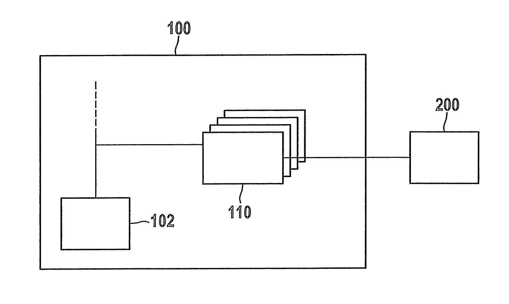
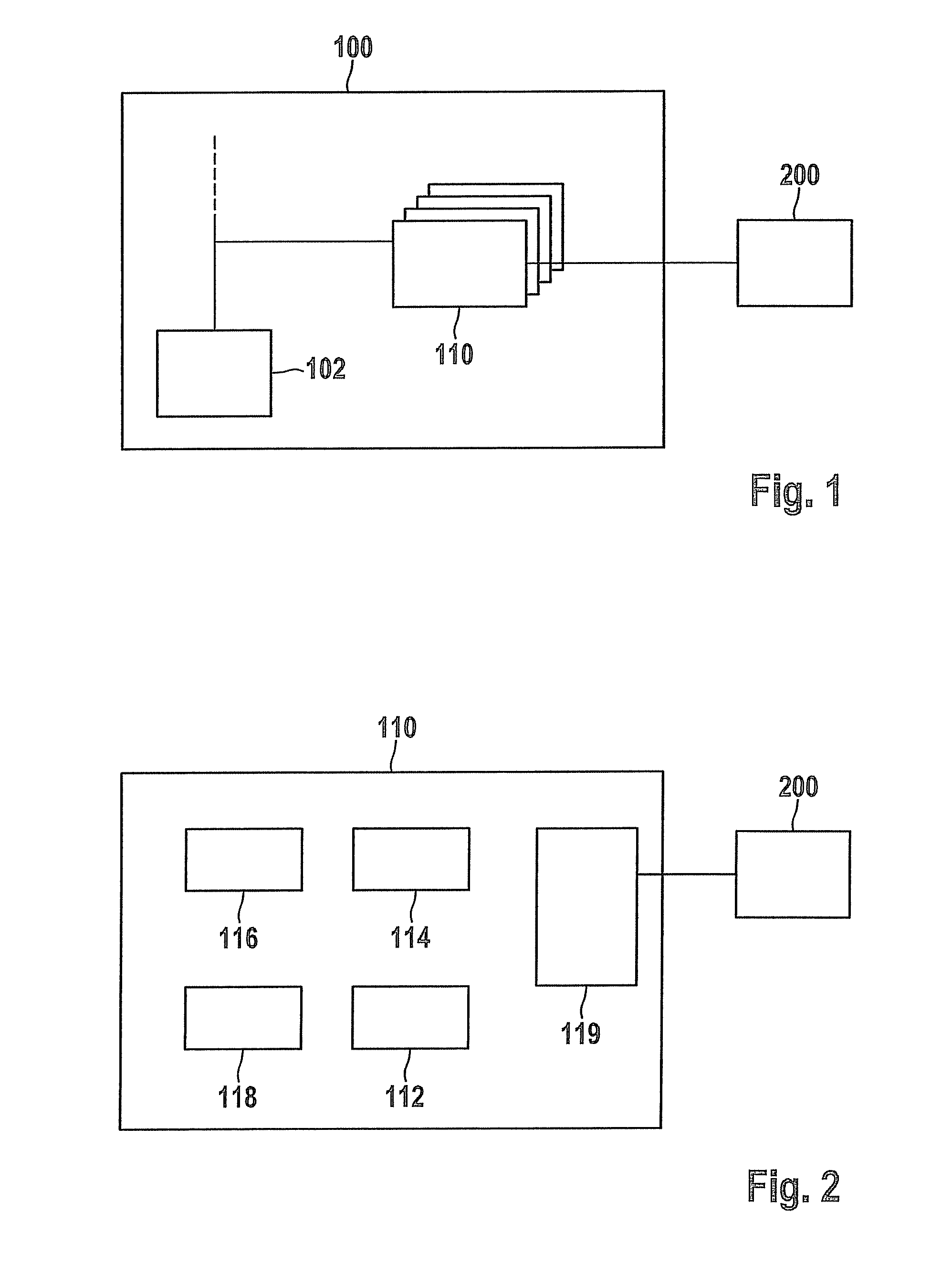
[0025]FIG. 1 shows schematically a block diagram of a control unit 100 according to the present invention. Control unit 100 is provided for the exchange of data with at least one peripheral unit 200, and may be used, for example, in the motor vehicle field, particularly for developing sensor networks and / or actuator networks. For example, peripheral unit 200 may be a sensor module which exchanges data with control unit 100 via a communications interface 110, that will be described in greater detail. Control unit 100 is able to evaluate these data directly, for instance, or only to process them and output them to an additional control unit (not shown).

[0026]According to one specific embodiment, control unit 100 is a control device that may be configured as a microcontroller or even as a digital signal processor (DSP), which is configured for controlling or regulating the operation of an internal combustion engine of a motor vehicle (engine control unit). Corresponding components of c...


PUM


Abstract

A control unit is described that has at least one communications interface for the exchange of data with at least one peripheral unit, the communications interface being configured for transmitting synchronization signals to the peripheral unit in a first, synchronous operating mode. The communications interface is configured to change a time interval between two successive synchronization signals.

Description

RELATED APPLICATION INFORMATION[0001]The present application claims priority to and the benefit of German patent application no. 10 2010 029 349.0, which was filed in Germany on May 27, 2010, the disclosure of which is incorporated herein by reference.FIELD OF THE INVENTION[0002]The present invention relates to s control unit having at least one communications interface for the exchange of data with at least one peripheral unit, the communications interface being configured for transmitting synchronization signals to the peripheral unit in a first, synchronous operating mode. The present invention also relates to a peripheral unit for the exchange of data with a control unit, as well as a method for exchanging data between a control unit and a peripheral unit.BACKGROUND INFORMATION[0003]Control units, peripheral units and operating methods of the type named above are known from the motor vehicle field, for example, the data being exchanged between peripheral units configured as sens...

Claims


Application Information

Patent Timeline
Patent Type & Authority Patents(United States)
IPC IPC(8): G06F13/42H04L12/40
CPCG06F13/4291H04L12/40084H04L12/40123H04L2012/40273H04L7/044
Inventor DAECKE, DIRKOPITZ, BERNHARDDOEHREN, STEFAN
Owner ROBERT BOSCH GMBH
Why Eureka
Try Eureka