Furniture for placing electronic device

a technology for placing electronic devices and furniture, applied in office tables, stilts, gymnastics, etc., can solve the problems of even unimaginable costs, and achieve the effect of muscles and joints, without hand hurting

Inactive Publication Date: 2007-04-12
CHEN CHAU LUNG
View PDF9 Cites 20 Cited by
  • Summary
  • Abstract
  • Description
  • Claims
  • Application Information

AI Technical Summary

Benefits of technology

[0009] In view of the above problem, an object of the present invention is to provide an article of furniture for placing an electronic device. The furniture for placing an electronic device provides a support board, which allows a user to control the electronic device with the hand at a pos

Problems solved by technology

However, it is known that a lot of money is spent on the treatment of musculoskeletal pains all over the world,

Method used


Image

  • Furniture for placing electronic device
  • Furniture for placing electronic device
  • Furniture for placing electronic device

Examples


second embodiment

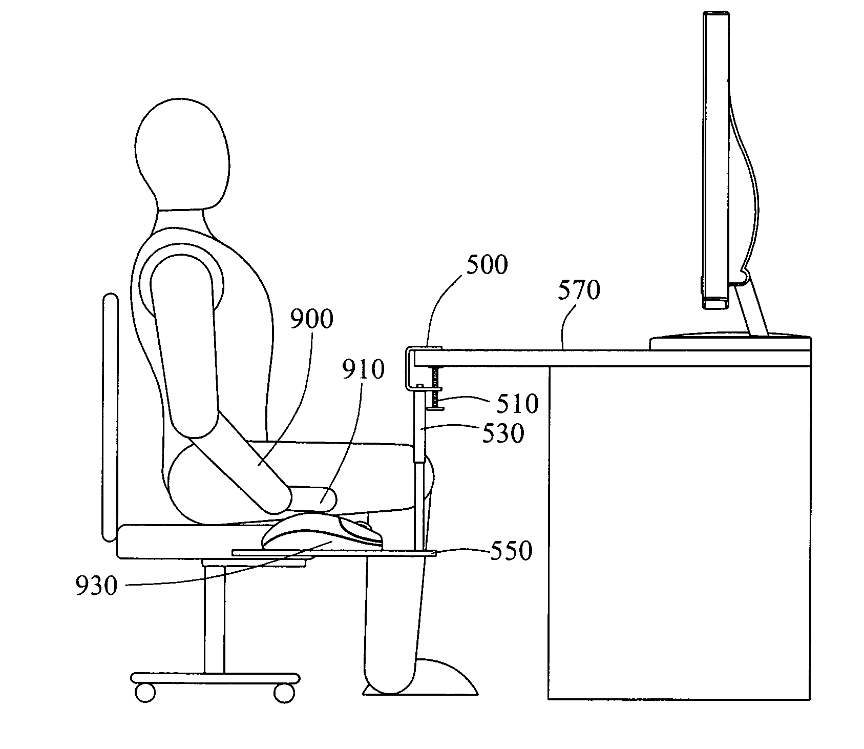
[0029]FIGS. 4 and 5 are respectively a schematic view of the present invention and a schematic view of the support board. Referring to FIGS. 4 and 5, the support board of the furniture for placing an electronic device in this embodiment uses a box-shaped body 500 to be clamped to the furniture component. The furniture component can be a plate 570 of the table that is screwed to one side of the box-shaped body 500 with a bolt 510. The bolt 510 is fastened against the plate 570, such that the box-shaped body 500 is fixed to the plate 570. One end of a connecting rod 530 is connected to one side of the box-shaped body 500 where the bolt 510 is fastened, and the other end of the connecting rod 530 is connected to a carrying board 550. The carrying board 550 is also located at the position where the user's palm 910 naturally drops down, such that when the user holds the mouse 930 with the palm 910, the mouse 930 is placed on the carrying board 550 for being operated. Thus, the arm 900 an...

third embodiment

[0030]FIG. 6 is a combined schematic view of the present invention. Referring to FIG. 6, the furniture component is a desk 700. A support board 710 is pivoted on the desk 700, and the support board 710 is located at the position where the user's hands naturally drop down. When the user holds the mouse 930 with the palm 910, and the mouse 930 is placed on the support board 710 for being used, the user's arm 900 and palm 910 are in a posture that meets the ergonomic requirements. Therefore, though the user operates the mouse 930 for a long time, the hand or shoulder will not hurt. To receive the support board 710 into the desk 700, an accommodation chute 701 is disposed on a rotating path of the desk 700 relative to the support board 710, so as to receive the support board 710 into the accommodation chute 701. When the support board 710 is needed to be used, it is drawn out.

fourth embodiment

[0031]FIGS. 7A and 7B are respectively a combined schematic view of the present invention and a top view of a chair. The furniture component is a chair 730, and a support board 750 is pivoted on the chair 730. The support board 750 is located at the position where the user's hands naturally drop down. When the user holds the mouse 930 with the palm 910, and the mouse 930 is placed on the support board for being used, the user's arm 900 and palm 910 are in a posture that meets the ergonomic requirements. Therefore, though the user operates the mouse 930 for a long time, the hand or shoulder will not hurt.

[0032] The support board 710 also can be received under the chair 730. When the support board 710 is not used, it is rotated to a position under the chair 730. When the support board 710 is needed to be used, it is pulled out again.


PUM


Abstract

An article of furniture for placing an electronic device is provided. The furniture provides a support board for placing an electronic device at a position of palms where a user's hands naturally drop down, such that the user operates the electronic device with the hand at the position where the hand naturally drop down. Thus, the user's hand muscles are relaxed. Although the user controls the electronic device with the hands for a long time, the hands do not hurt.

Description

CROSS-REFERENCE TO RELATED APPLICATIONS [0001] This non-provisional application claims priority under 35 U.S.C. § 119(a) on Patent Application No(s). 094217453 filed in Taiwan, R.O.C. on Oct. 7, 2005, the entire contents of which are hereby incorporated by reference. BACKGROUND OF THE INVENTION [0002] 1. Field of Invention [0003] The present invention relates to a furniture structure for placing an electronic device, and more particularly, to a furniture structure for placing an electronic device that allows a user to operate the electronic device when the user's hands naturally drop down. [0004] 2. Related Art [0005] Nowadays, people are rich, and enjoy the high-quality life. However, diseases do not become diminished as the progress of the times; instead, people are suffering from more diseases. Besides diseases caused by bacteria, a new term “disease of civilization” has been put forward in recent years, which is caused by the change of life styles and habits. Especially, as comp...

Claims


Application Information

Patent Timeline
IPC IPC(8): A63B26/00A47B83/02
CPCA47B21/0314
Inventor CHEN, CHAU-LUNG
Owner CHEN CHAU LUNG
Why Eureka
Try Eureka