Supporting device for placing an electronic device

a technology for supporting devices and electronic devices, applied in combination furniture, office tables, cabinets, etc., can solve the problems of even unimaginable costs, and achieve the effect of not hurting the hand

Inactive Publication Date: 2007-07-26
CHEN CHAU LUNG
View PDF9 Cites 3 Cited by
  • Summary
  • Abstract
  • Description
  • Claims
  • Application Information

AI Technical Summary

Benefits of technology

[0010] In view of the above problem, an object of the present invention is to provide a supporting device for placing an electronic device. The supporting device allows a user to control the electronic device with the hand at a position where the hand naturally drop down and the palm having a horizontal tilt, such that the user's arm has a natural dropping motion and the forearm has a natural motion without being twisted. The muscles and joints of the user are kept in a relaxed state. Thus, the ergonomic requirements are met, and the user's hands can operate the electronic device for a long time without making the hand hurt.
[0012] Therefore, as for a user who has to operate an electronic device with the same posture for a long time, the present invention guides the user to naturally drop down the shoulders and keep the elbows higher than the wrists when operating the electronic device. The user's palm naturally tilts because the support board has a horizontal tilt, such that the user's forearm is relaxed without being twisted. When a user operates an electronic device placed on the support board, whether in a sitting posture or a standing posture, if the arms are kept at a normal physiological position, i.e., the shoulders and elbows naturally drop down, the wrists are lower than the elbow joints, and the forearm is relaxed, the user only needs to flex the thumb and adduct the thumb, and flex the finger tips to operate the electronic device. Thus, the motions for the scapulas, shoulders, elbows, wrists, forearm, and a part of the finger joints to exert forces are omitted, so that the muscles that are originally participated in the motions when the hands are raised are no longer continuously kept in the contracted state as the hands naturally drop down. Thus, the risks of neck rigidity, pain of the upper back, pains of the shoulder, elbow, wrist joints, and forearm, De Quervain's disease, and even carpal tunnel syndrome are relatively avoided.
[0013] However, it is known that a lot of money is spent on the treatment of musculoskeletal pains all over the world, and if certain surgeries and long-time recovery are taken into consideration, the cost will be even unimaginable. Therefore, the present invention allows a user who has to maintain the same posture for a long time to change the method of operating the electronic device in an ergonomic manner, so as to relieve the diseases of joints and muscles caused by wrong postures. Thus, the present invention helps users to maintain the health and eliminate the sores and pains, and helps employers to enhance the employees' working efficiency and thereby creating more benefits. As for the features and examples of the present invention, the preferred embodiment will be illustrated below in detail with reference to the drawings.

Problems solved by technology

However, it is known that a lot of money is spent on the treatment of musculoskeletal pains all over the world, and if certain surgeries and long-time recovery are taken into consideration, the cost will be even unimaginable.

Method used


Image

  • Supporting device for placing an electronic device
  • Supporting device for placing an electronic device
  • Supporting device for placing an electronic device

Examples


first embodiment

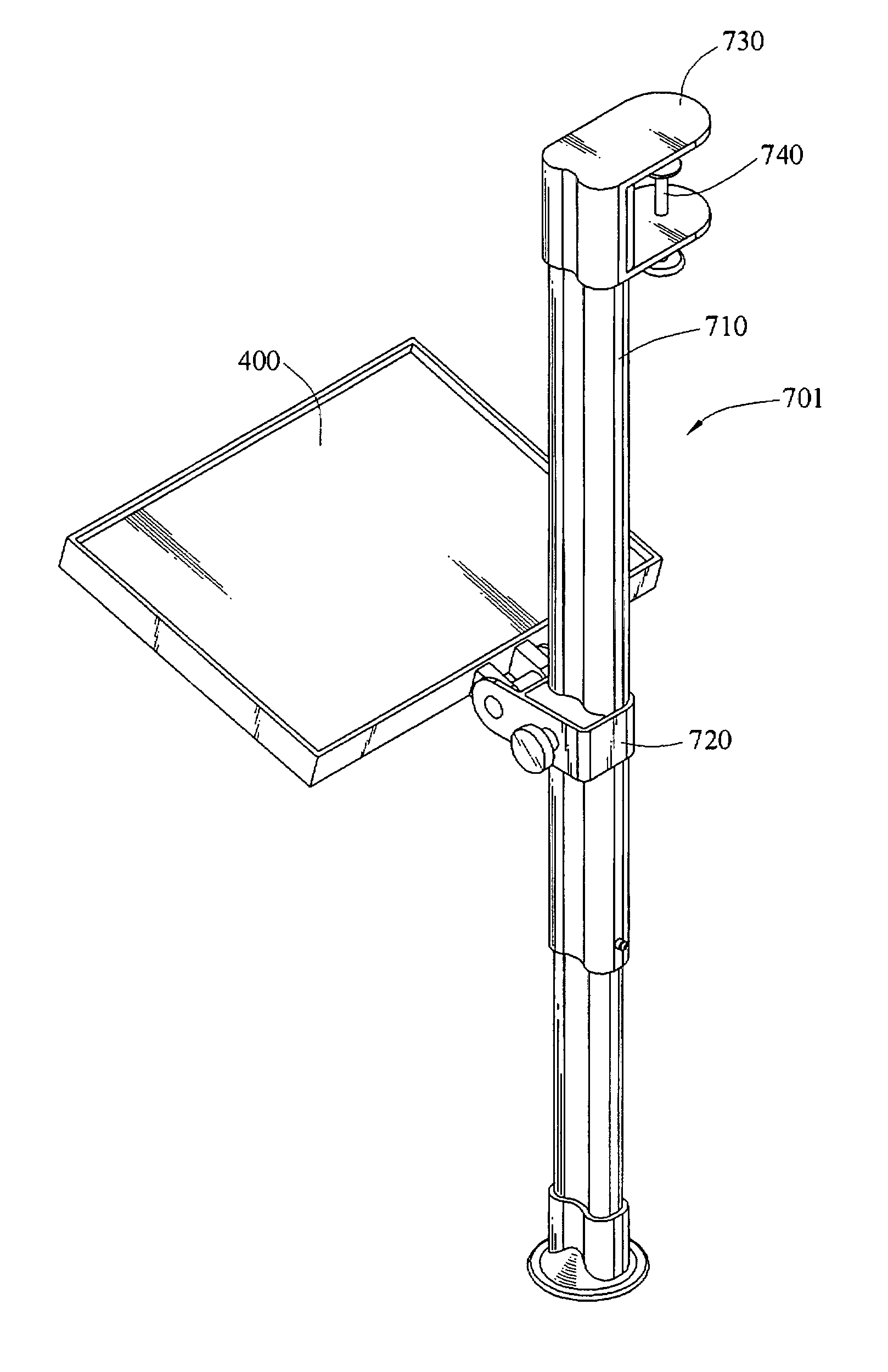
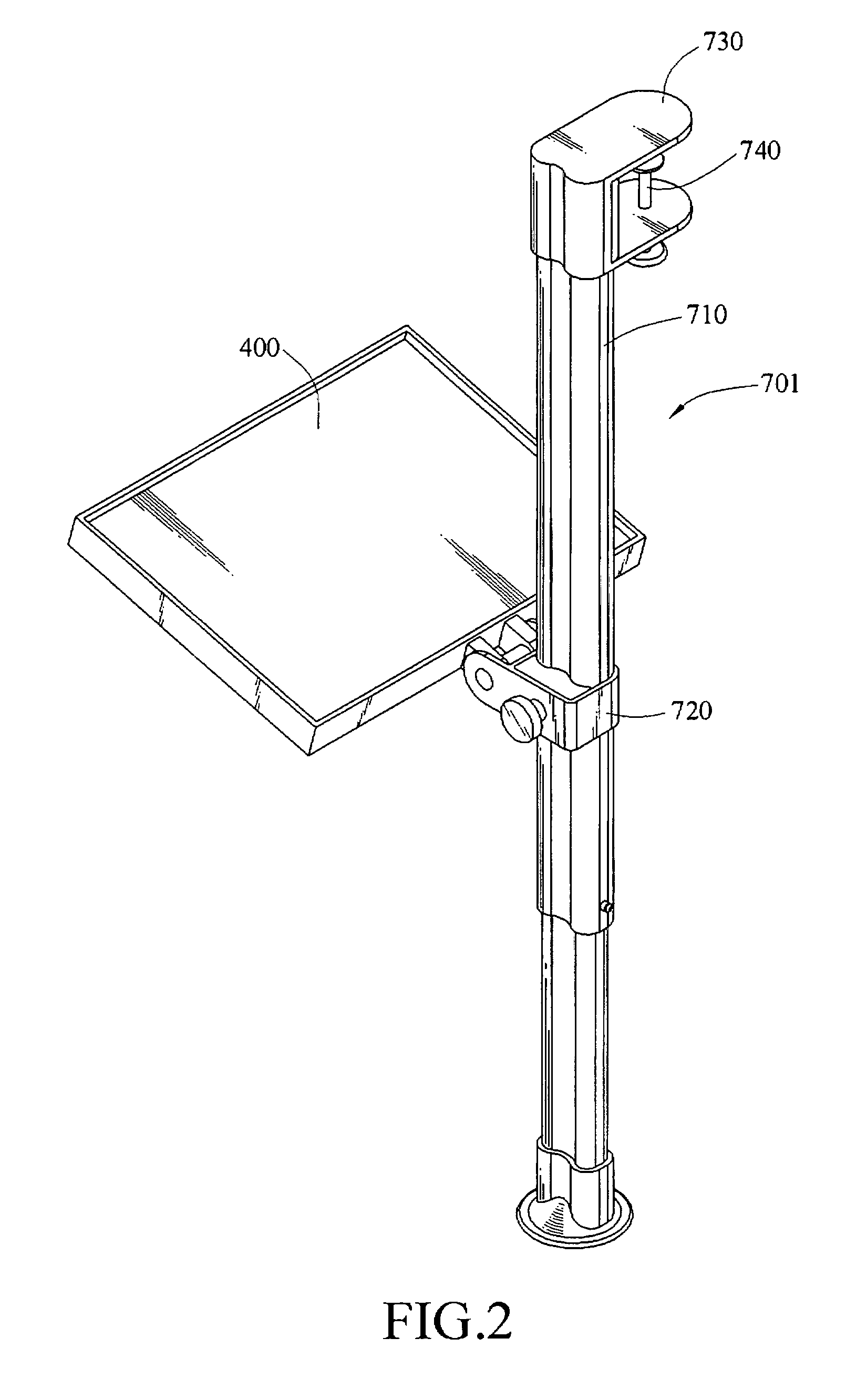
[0028] Referring to FIGS. 2, and 3, the support supporting device according to the present invention is provided. The connecting member 701 includes a telescopic bar 710 and a sliding member 720. One end of the telescopic bar 710 is connected to the furniture component, which is a table 390 in this embodiment, and the other end of the telescopic bar 710 is stationed on the ground. The length of telescopic bar 710 in this embodiment can be adjusted, which is convenient for the storage or meeting the height of different tables. The sliding member 720 is a sleeve slid over the telescopic bar 710, such that the sliding member 720 is movably disposed on the telescopic bar 710, for being moved to a position where the user's hands naturally drop down.

[0029] The support board 400 is pivotally connected to the sliding member 720, and is able to be rotated according to a rotational axis toward the front of the user to have a horizontal tilt. The support board 400 is used for placing a mouse 9...

second embodiment

[0033] Referring to FIGS. 4, 5A, and 5B, a supporting device of the present invention is provided, which includes a connecting member 301 and a support board 400. The connecting member 301 includes a fixing board 300 and a carrying frame 310. The fixing board 300 is fixed on the table 390, and the carrying frame 310 has a hollow area 311, wherein the support board 400 is pivotally connected to the carrying frame 310 and located at the hollow area 311. The support board 400 is used for placing a mouse 930, such that the mouse 930 is operated on the support board 400. Furthermore, the carrying frame 310 with the support board 400 in this embodiment can be folded, which is convenient for the storage, as shown in FIG. 5B. A connecting link 330 is used to connect the fixing board 300 with the carrying frame 310. One end of the connecting link 330 is pivoted on one side of the fixing board 300, and the other end of the connecting link 330 is pivoted on one side of the carrying frame 310, ...

third embodiment

[0037] Referring to FIGS. 6 and 7, a supporting device of the present invention is provided, which includes a connecting member 501 and a support board 400. The connecting member 501 includes a clamping body 500, a bolt 510, connecting rod 530, and a carrying body 550. The clamping body 500 is used for clamping the furniture component. The furniture component can be a plate 570 of the table. The bolt 510 is screwed to one side of the clamping body 500, wherein the bolt 510 is fastened against the plate 570, such that the clamping body 500 is fixed to the plate 570. One end of the connecting rod 530 is connected to one side of the clamping body 500 where the bolt 510 is fastened, and the other end of the connecting rod 530 is connected to the carrying body 550.

[0038] The carrying body 550 is located at the position where the user's palm 910 naturally drops down, and the support board 400 is pivotally connected to the carrying body 550 for placing the mouse 930. The support board 400 ...


PUM


Abstract

A supporting device is provided, which is disposed on a furniture component for placing an electronic device. The supporting device includes a connecting member and a support board. The connecting member is connected to the furniture component, while the support board for placing an electronic device is pivotally connected to the connecting member. The support board is located at a position of palms where a user's hands naturally drop down, and is able to be rotated according to a rotational axis toward the front of the user, so as to have a horizontal tilt, such that the user's palm naturally tilts to hold the electronic device without the user putting forth his strength. Thus, the user's arm muscles are relaxed. Although the user controls the electronic device with the hands for a long time, the hands do not hurt.

Description

CROSS-REFERENCE TO RELATED APPLICATIONS [0001] This non-provisional application claims priority under 35 U.S.C. §119(a) on Patent Application No(s). 094217453 filed in Taiwan, R.O.C. on Oct. 7, 2006, the entire contents of which are hereby incorporated by reference. [0002] This application is a continuation-in-part patent application of U.S. application Ser. No. 11 / 543,155 filed on Oct. 5, 2006, the entire contents of which are hereby incorporated by reference for which priority is claimed under 35 U.S.C. §120.BACKGROUND OF THE INVENTION [0003] 1. Field of Invention [0004] The present invention relates to a supporting device for placing an electronic device, and more particularly, to a supporting device disposed on a furniture component for placing an electronic device that allows a user to operate the electronic device when the user's hands naturally drop down with a horizontal tilt. [0005] 2. Related Art [0006] Nowadays, people are rich, and enjoy the high-quality life. However, d...

Claims


Application Information

Patent Timeline
Patent Type & Authority Applications(United States)
IPC IPC(8): A47B57/00A47B83/02
CPCA47B21/0314
Inventor CHEN, CHAU-LUNG
Owner CHEN CHAU LUNG
Why Eureka
Try Eureka