Industrial two-layer fabric

a two-layer fabric and fabric technology, applied in the field of industrial two-layer fabrics, can solve the problems of fabric also having a problem, short life, and increased requirements for papermaking fabrics, and achieve excellent water drainage properties

Active Publication Date: 2007-05-03
NIPPON FILCON
View PDF29 Cites 27 Cited by
  • Summary
  • Abstract
  • Description
  • Claims
  • Application Information

AI Technical Summary

Benefits of technology

[0018] The industrial two-layer fabric according to the present invention which is free from partially uneven wear and having excellent water drainage property, fiber supporting property and the like can be obtained by shifting, with certain regularity, the design of one lower surface side weft having rigidity and wear resistance.

Problems solved by technology

In recent years, owing to the speed-up of a papermaking machine, requirements for papermaking fabrics become more severe.
A crimp of lower surface side wefts which is brought into contact with a machine or roll is however short and does not protrude sufficiently so that a wear resistant volume of this fabric is small, which results in a problem of short lifetime.
However, this fabric also has a problem.
Compared with the fabric of a ribbed weave design, this fabric has less weaving positions, which reduces its rigidity.
In addition, wefts cannot be fixed firmly and undesirable movement occurs owing to a too long crimp of lower surface side wefts.
As a result, the fabric does not have greatly improved lifetime in spite of an increase in the wear resistant volume of wefts.
A lower surface side warp approaches lower surface side warps right adjacent and left adjacent thereto successively and is thus disposed in a zigzag manner so that the fabric has improved rigidity, but the undesirable movement of wefts cannot be prevented because of a too long crimp.
As a result, wear of this portion precedes wear of the other portion.
Owing to subsequent breakage, the fabric becomes unsuited for practical use.
In short, although a fabric excellent in rigidity and free of undesirable movement of wefts can be obtained, wear resistance is not sufficient owing to partially uneven wear.
A papermaking fabric capable of satisfying such severe demands has not yet been developed.

Method used


Image

  • Industrial two-layer fabric
  • Industrial two-layer fabric
  • Industrial two-layer fabric

Examples


example 1

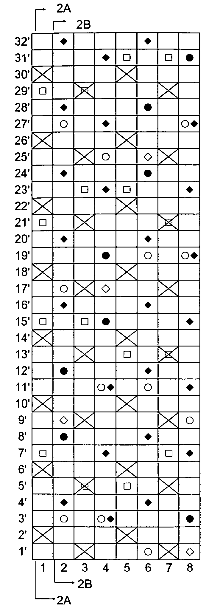
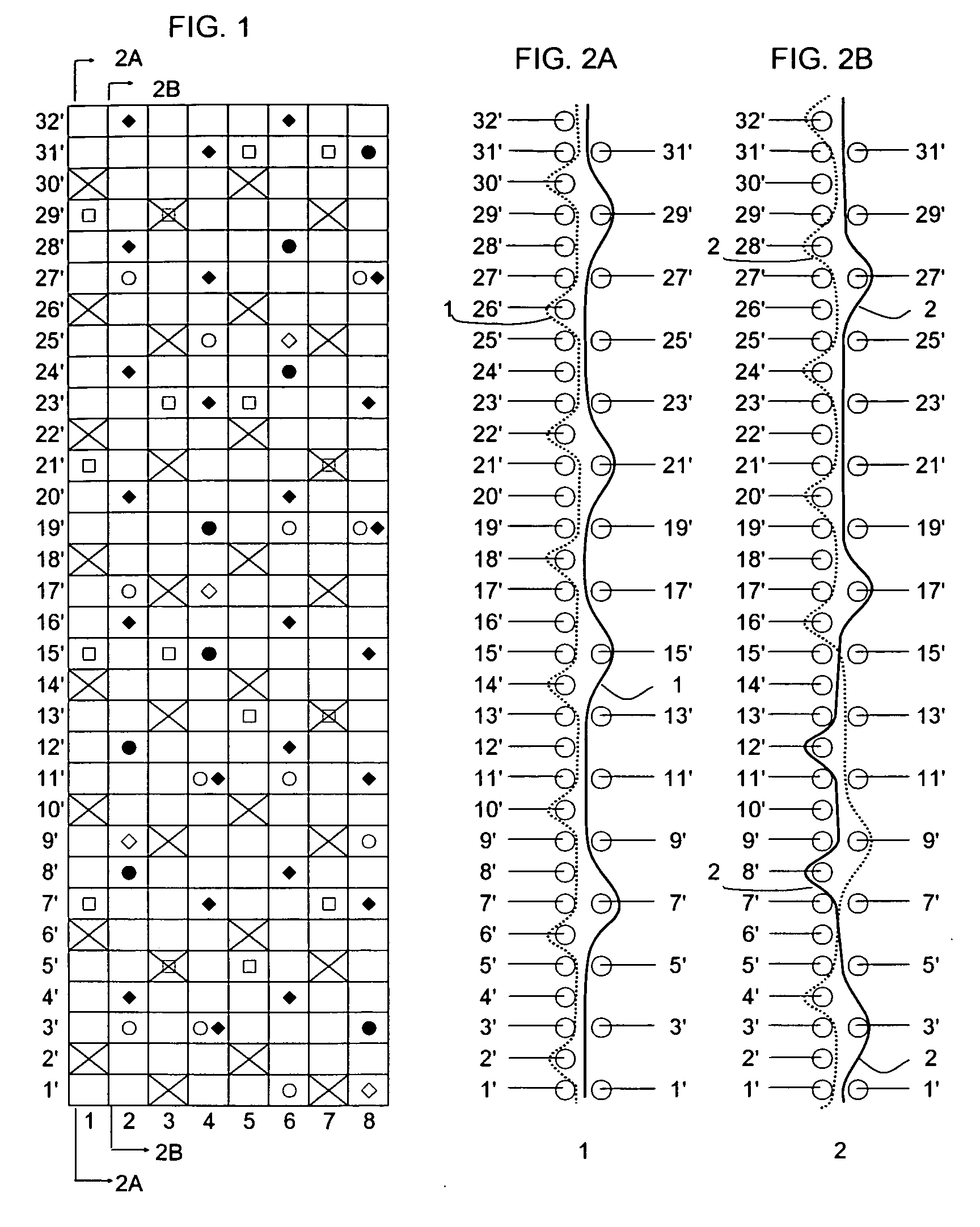
[0068]FIG. 1 is a design diagram of a fabric of Example 1 of the present invention. FIGS. 2A and 2B include cross-sectional views taken along the lines 2A-2A and 2B-2B of the warp pair 1 and binding warp pair 2 illustrated in the design diagram of FIG. 1 respectively. This fabric is woven by the pair of two warp binding yarns and it has a complete design formed by four binding warp pairs 2, 4, 6 and 8 and four warp pairs 1, 3, 5 and 7.

[0069] The fabric has, as an upper side layer, a sateen weave design obtained by shifting, with a certain regularity, a 1 / 3 design in which a warp passes over one upper surface side weft and then passes under three upper surface side wefts. Upper surface side wefts and lower surface side wefts are arranged at a ratio of 2:1.

[0070] In the design diagram of FIG. 1, indicated by numerals 2, 4, 6 and 8 are each a binding warp pair composed of two warp binding yarns, while indicated by numerals 1, 3, 5 and 7 are warp pairs composed of an upper surface sid...

example 2

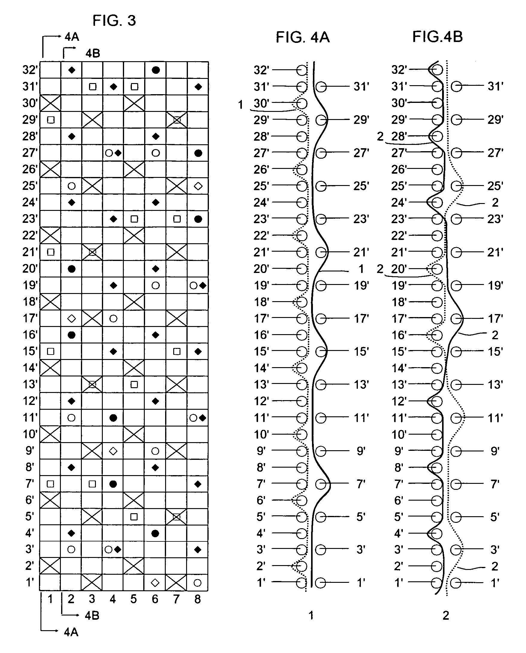
[0081]FIG. 3 is a design diagram illustrating a fabric of Example 2 according to the present invention. FIGS. 4A and 4B include cross-sectional views taken along the lines 4A-4A and 4B-4B of the warp pair 1 and the binding warp pair 2 illustrated in the design diagram of FIG. 3 respectively. The fabric of this example is woven by a pair of two warp binding yarns and four bind warp pairs and four warp pairs constitute its complete design.

[0082] The upper side layer of this fabric has a sateen weave design obtained by shifting, with certain regularity, a 1 / 3 design in which a warp passes over an upper surface side weft and passes under three upper surface side wefts. Upper surface side wefts and lower surface side wefts are arranged at a ratio of 2:1.

[0083] In the design diagram of FIG. 3, indicated by numerals 2, 4, 6 and 8 are binding warp pairs composed of two warp binding yarns, while indicated by numerals 1, 3, 5 and 7 are warp pairs composed of an upper surface side warp and a...

example 3

[0089]FIG. 5 is a design diagram illustrating a fabric of Example 3 according to the present invention. FIGS. 6A and 6B include cross-sectional views taken along the lines 6A-6A and 6B-6B of the warp pair 1 and the binding warp pair 2 illustrated in the design diagram of FIG. 5 respectively. The fabric of this example has a complete design formed by two binding warp pairs and six warp pairs. The binding warp pair is composed of a warp binding yarn and a lower surface side warp. The upper side layer of this fabric has a sateen weave design obtained by shifting, with certain regularity, a 1 / 3 design in which a warp passes over an upper surface side weft and then, passes under three upper surface side wefts. Upper surface side wefts and lower surface side wefts are arranged at a ratio of 2:1.

[0090] In the design diagram of FIG. 5, indicated by numerals 2 and 6 are binding warp pairs composed of a warp binding yarn and a lower surface side warp, while indicated by numerals 1, 3, 4, 5, ...


PUM


Abstract

An industrial two-layer fabric having a lower surface structure excellent in water drainage property, fiber supporting property, rigidity and wear resistance, obtained by binding an upper layer fabric and a lower layer fabric, wherein each of lower surface side wefts has a design in which it passes over one lower surface side warp, passes under one lower surface side warp, passes over one lower surface side warp and then passes under five successive lower surface side warps, while lower surface side warps each has a design in which it passes over four successive lower surface side wefts, passes under one lower surface side weft, passes over three successive lower surface side wefts, passes under one lower surface side weft, passes over two successive lower surface side wefts, passes under one lower surface side weft, passes over three successive lower surface side wefts and then passes under one lower surface side weft.

Description

BACKGROUND OF THE INVENTION [0001] The present invention relates to industrial two-layer fabrics excellent in rigidity, water drainage property, wear resistance, fiber supporting property and yield, and can be used for a long period of time. [0002] Fabrics woven by warps and wefts have conventionally been used widely as an industrial fabric. They are, for example, used in various fields including papermaking wires, conveyor belts and filter cloths so that they are required to have fabric properties suited for the intended use or using environment. Particularly, papermaking fabrics used in a paper making step for removing water from raw materials by making use of the network of the fabric must satisfy a severe demand. There is therefore a demand for the development of fabrics which do not transfer a wire mark of the fabric to paper and therefore have excellent surface property, have dehydration property for sufficiently removing extra water contained in the raw materials, have enough...

Claims


Application Information

Patent Timeline
Patent Type & Authority Applications(United States)
IPC IPC(8): D03D25/00
CPCD03D11/00D21F1/0036Y10S162/903Y10S162/901
Inventor FUJISAWA, SHIGENOBU
Owner NIPPON FILCON
Why Eureka
Try Eureka