Light emitting device

Inactive Publication Date: 2007-05-03
LEADRAY ENERGY
View PDF13 Cites 111 Cited by
  • Summary
  • Abstract
  • Description
  • Claims
  • Application Information

AI Technical Summary

Benefits of technology

[0006] Therefore, the object of the present invention is to provide a light emitti

Problems solved by technology

As such, heat dissipating efficiency of the conventional light emitting assembly is poor due to the inclusion of the thermally conductive paste and the silicone adhesive, which, in turn, results in a decrease in the service life of the light emitting assembly.
In addition, since the light emitting devices are adhered to the circuit board, replacement of a damaged one of the light emitting devices on the circuit board is relatively inconvenient.

Method used


Image

  • Light emitting device
  • Light emitting device
  • Light emitting device

Examples


Embodiment Construction

[0024] Before the present invention is described in greater detail with reference to the accompanying preferred embodiments, it should be noted herein that like elements are denoted by the same reference numerals throughout the disclosure.

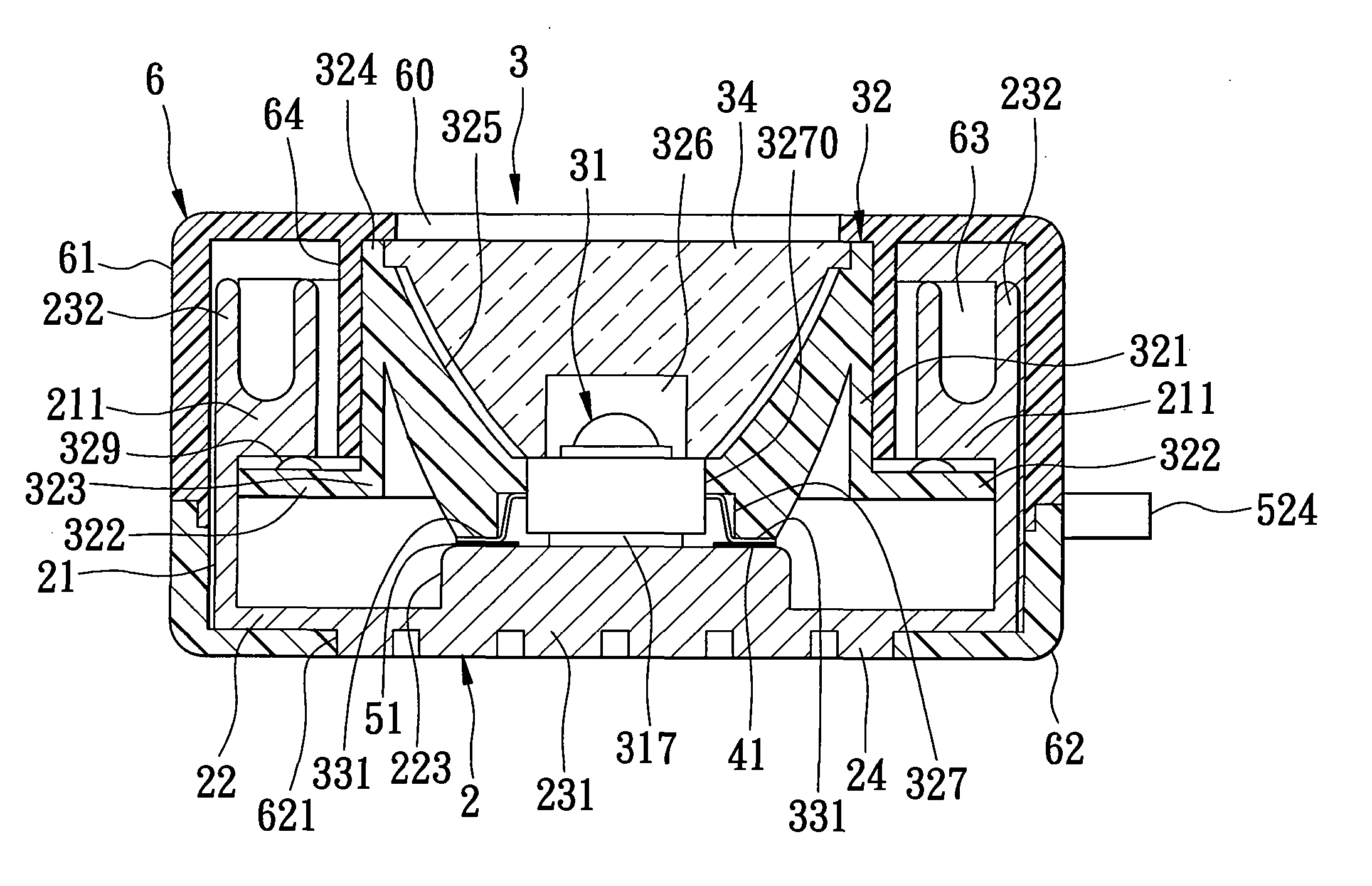
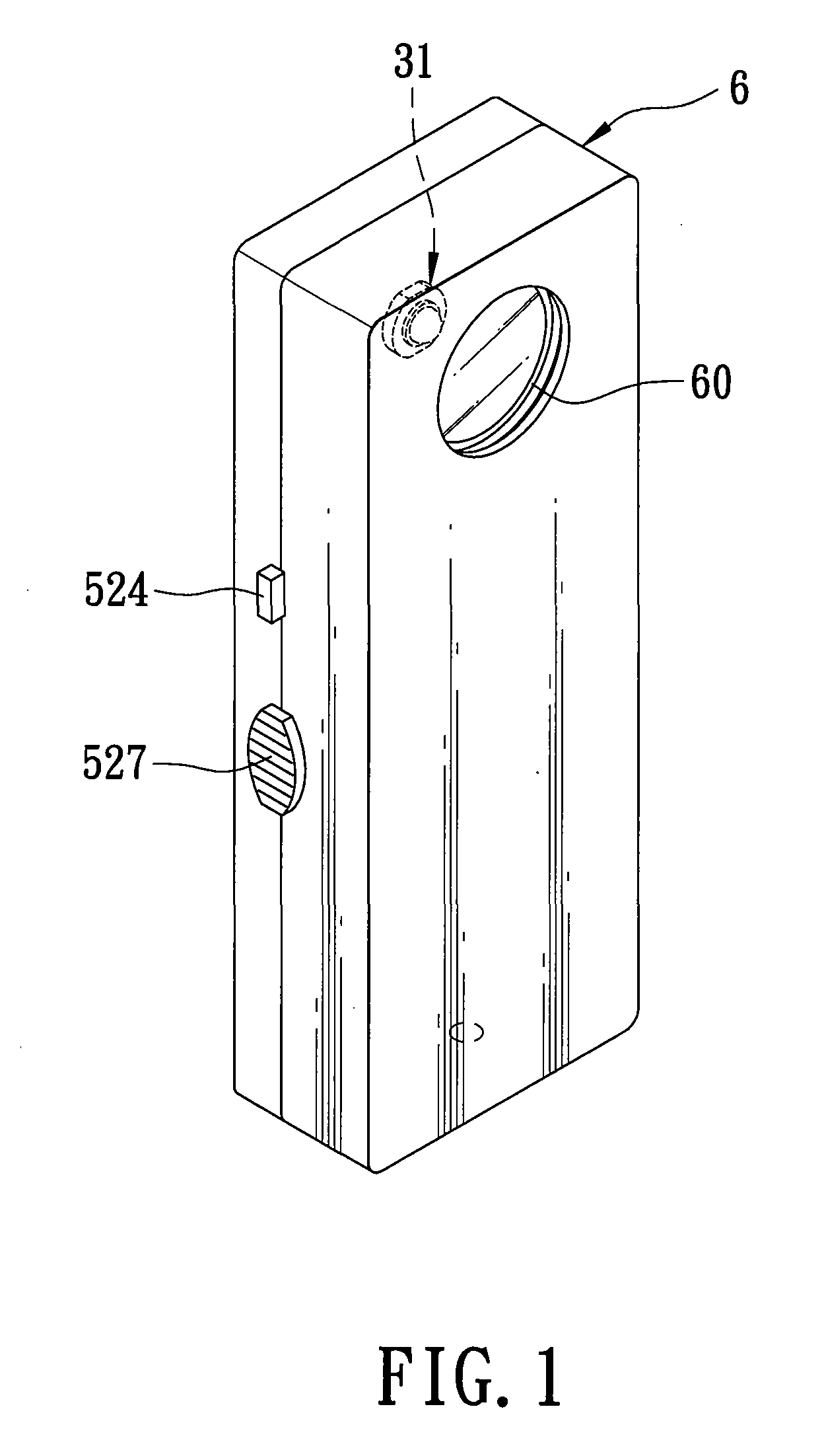
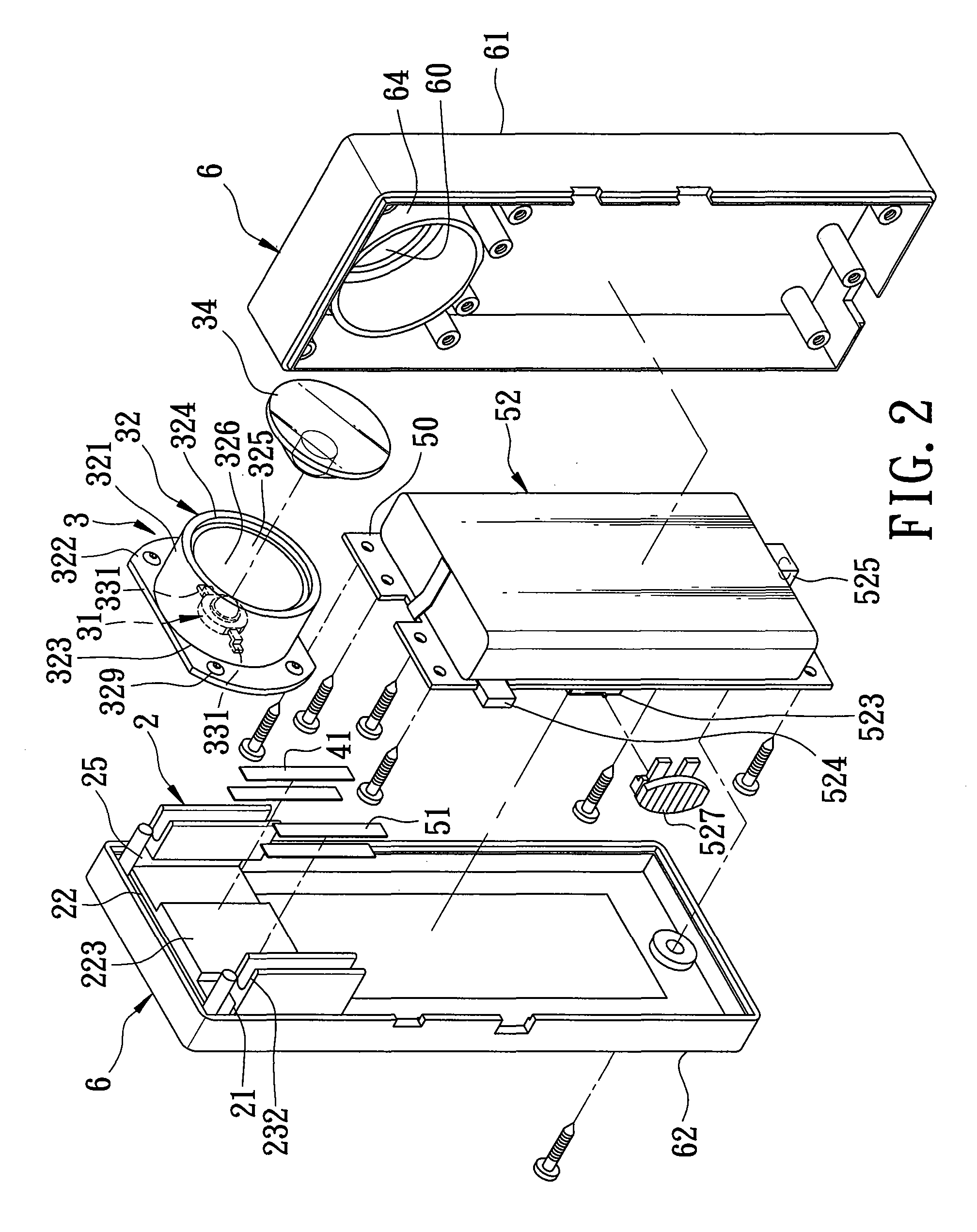
[0025] FIGS. 1 to 4 illustrate the first preferred embodiment of a light emitting assembly according to the present invention. The light emitting assembly includes: a heat sink 2 including a base wall 22 and two opposite retaining walls 21 extending upright from two opposite sides of the base wall 22 and defining respectively two retaining grooves 25, each of the retaining walls 21 having a top wall portion 211 confining a top side of a respective one of the retaining grooves 25; and a light emitting unit 3 mounted on the heat sink 2. The light emitting unit 3 includes a mounting seat 32 having two opposite wings 322 extending oppositely and respectively into the retaining grooves 25, and a light emitting device 31 mounted on the mounting seat 32 ...


PUM


Abstract

A light emitting assembly includes: a heat sink including a base wall and two opposite retaining walls extending upright from the base wall and defining respectively two retaining grooves, each of the retaining walls having a top wall portion confining a top side of a respective one of the retaining grooves; a mounting seat having two opposite wings extending respectively into the retaining grooves; and a light emitting device mounted on the mounting seat and having a bottom wall extending through the mounting seat to abut against the base wall of the heat sink. Each of the wings of the mounting seat is formed with an elastic protrusion that abuts resiliently against the top wall portion of a respective one of the retaining walls.

Description

CROSS-REFERENCE TO RELATED APPLICATION [0001] This application claims priority of Taiwanese Application No. 094138111, filed on Oct. 31, 2005. BACKGROUND OF THE INVENTION [0002] 1. Field of the Invention [0003] The invention relates to a light emitting device, more particularly to a light emitting device having a heat sink with two retaining grooves and a mounting seat with two wings extending into the retaining grooves, respectively. [0004] 2. Description of the Related Art [0005] Conventional light emitting assembly normally includes a plurality of light emitting devices mounted on a circuit board, and a fined heat sink for dissipating heat resulting from the light emitting devices. Attachment of the light emitting devices to the circuit board is normally achieved through thermally conductive paste, and attachment of the circuit board to the heat sink is achieved through silicone adhesive. As such, heat dissipating efficiency of the conventional light emitting assembly is poor due...

Claims


Application Information

Patent Timeline
IPC IPC(8): G02B6/36H01L33/58H01L33/60H01L33/62H01L33/64
CPCF21K9/00F21S4/008F21S48/328F21V21/34F21V29/004F21Y2101/02F21V29/763F21V19/0035F21V19/004F21V19/0045F21V29/73F21V29/75F21L4/08F21S4/28F21Y2115/10
Inventor CHEN, KUEI-FANG
Owner LEADRAY ENERGY
Why Eureka
Try Eureka