Countersink gauge having self-centering probe

a self-centering, counter-sink technology, applied in the direction of measurement gauges, instruments, measurement devices, etc., can solve the problems of measurement error and error, and achieve the effect of reliable and accurate feature measuremen

Inactive Publication Date: 2007-05-10
THE BOEING CO
View PDF8 Cites 16 Cited by
  • Summary
  • Abstract
  • Description
  • Claims
  • Application Information

AI Technical Summary

Benefits of technology

[0007] According to still another aspect of the invention, a device is provided for measuring a feature of a countersink formed in a workpiece hole using a countersink tool and a guide fixture for aligning the tool. The device comprises an indicator assembly positioned on the guide fixture, a displaceable probe for contacting walls of the countersink, and a centering connector connecting the indicator assembly with the probe. The connector transmits displacement of the probe to the ind...

Problems solved by technology

A number of gauge devices exist for measuring features of countersinks, such as depth and diameter, however these prior devices sometimes yield erroneous measurements due to the fact that a probe forming part of the gauge is not precisely centered within the countersink hole opening.
This misalignment problem stems from the fact that gauges are normally used in combination with fixtures that are used to drill the countersink hole.
However, ...

Method used


Image

  • Countersink gauge having self-centering probe
  • Countersink gauge having self-centering probe
  • Countersink gauge having self-centering probe

Examples


Embodiment Construction

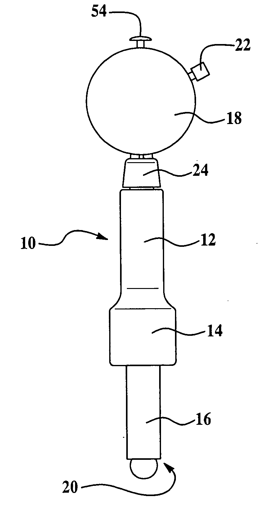
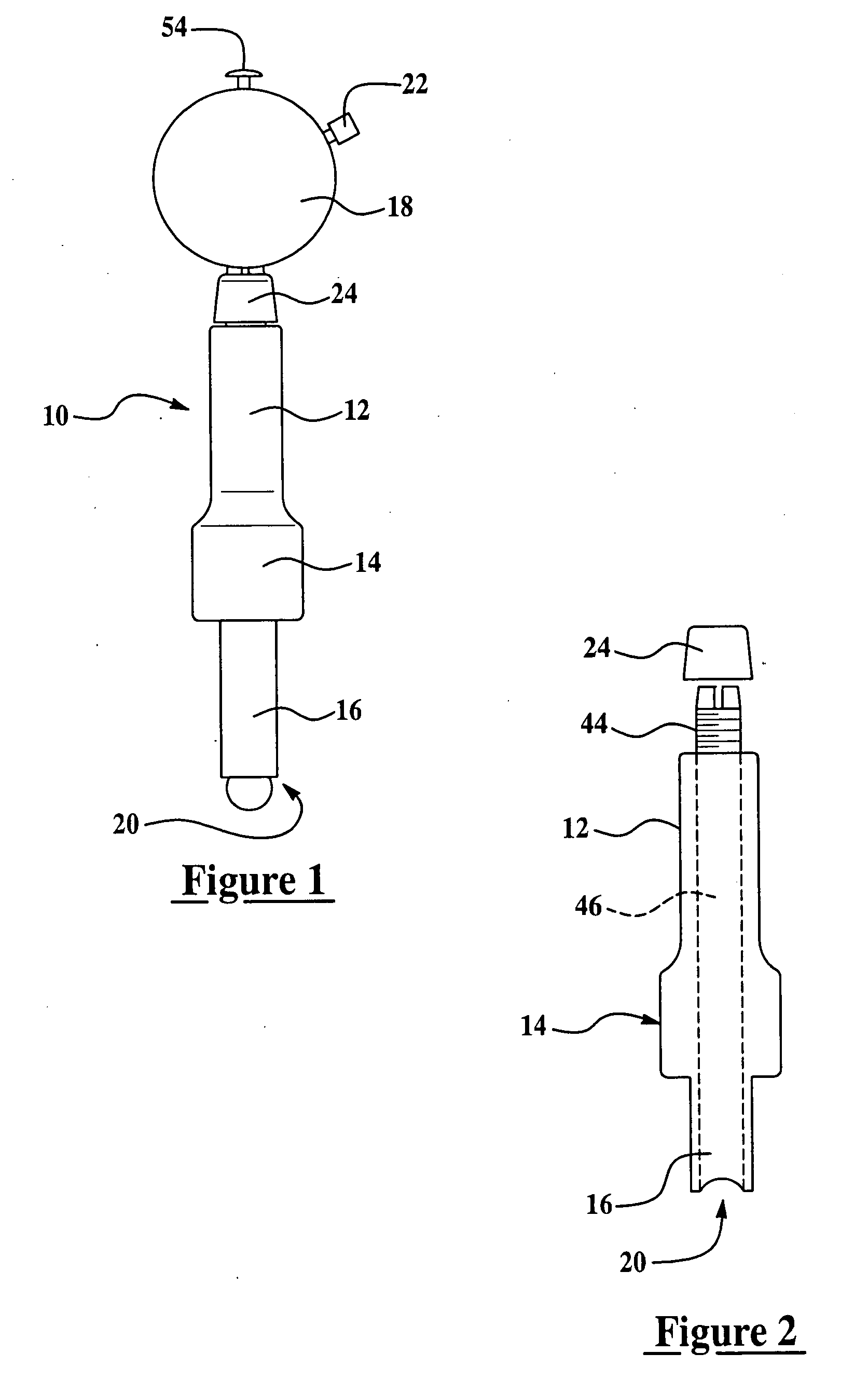
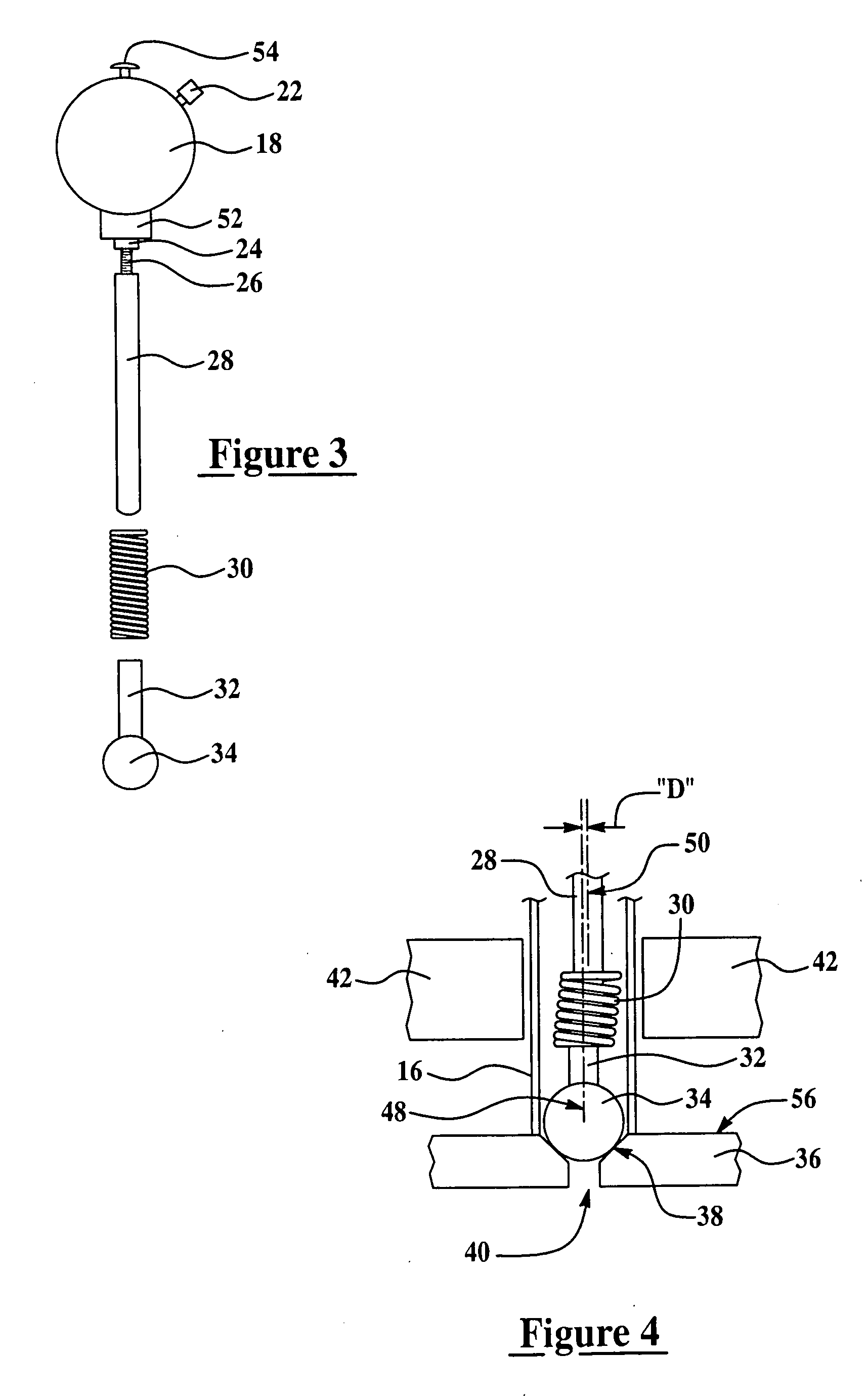
[0013] Referring to the drawings, a countersink gauge generally indicated by the numeral 10 in FIG. 1 includes an analog indicator 18 for indicating the measurement of a feature such as the countersink diameter, and an elongate body in the form of a tube 12. The tube 12 includes an intermediate knurled section 14 intended to be gripped by a operator, and a lower end 16 in which a later discussed probe 34 is contained. The tube 12 is secured to the indicator 18 by means of a split collet 44 and nut 24 which is sleeved over a short cylindrical extension 52 at the bottom of the indicator 18. Tightening of the nut 24 squeezes the collet 44 onto the extension 52, thus securing the tube 12 on the indicator 18. The tube 12 includes a central, cylindrical bore 46 throughout its entire length. The lower end 16 of tube 12 is provided with a series of actuate cutouts or scallops 20. A screw 22 on the indicator 18 allows rotational adjustment of the face of the indicator 18, and is typically us...


PUM


Abstract

A feature of a countersink in a hole, such as the diameter, is measured by a gauge having a self centering, spherically shaped probe which shifts laterally upon engagement with the countersink side walls to as to align itself with the central axis of the hole. The gauge includes an outer tube gripped by a user during the measurement, and an axially displaceable shaft within the tube that drives an indicator dial. The shaft is coupled with the probe by a flexible connector which transmits axial displacement of the probe to the shaft but allows slight lateral movement of the probe relative to the shaft, permitting the probe to become centered within the countersink.

Description

FIELD OF THE INVENTION [0001] This invention generally relates to measurement of workpiece features, and deals more particularly with a gauge having a self-centering probe for measuring a feature of a hole countersink. BACKGROUND OF THE INVENTION [0002] Countersink holes are commonly used throughout industry where it is necessary or desirable to recess the head of a fastener, such as a screw or rivet. For example, countersink holes are extensively employed in the aircraft industry, where rivets are used to attach an outer skin to frame members. In this application, it is particularly important that the top of the rivet be flush with the outer surface of the skin, otherwise non-flush rivets disturb the air flow over the skin, creating turbulence which adds drag to the aircraft. Consequently, it is important that the tapered side walls of the hole countersink have a precise depth calculated so that the top of the rivet is precisely flush with the skin surface. [0003] A number of gauge...

Claims


Application Information

Patent Timeline
IPC IPC(8): G01B3/00
CPCG01B3/28
Inventor NAPPIER, DAVID N.
Owner THE BOEING CO
Why Eureka
Try Eureka