Vehicle for enhancing recognition accuracy of visual information

a technology for visual information and vehicles, applied in the field of vehicles, can solve the problems of reduced visibility of red light, and strong fatigue and drowsiness of drivers, and achieve the effect of increasing the brightness contrast of red light and increasing the visibility of red ligh

Inactive Publication Date: 2007-05-10
HONDA MOTOR CO LTD
View PDF19 Cites 14 Cited by
  • Summary
  • Abstract
  • Description
  • Claims
  • Application Information

AI Technical Summary

Benefits of technology

[0043] In accordance with such the configuration, because the third area has a light transmission characteristic of attenuating light in a wavelength range of 520 nm to 570 nm by not less than 50%, it can attenuate shorter wavelength light than red such as yellow and green. Thus a brightness contrast of red light used in such a traffic signal and a brake lamp of a preceding vehicle is enhanced, and the visibility of the red light is increased.

Problems solved by technology

At this time, if scenery around is too seeable, driver's fatigue and drowsiness become strong in some case.
However, because the device recited in the Japanese Patent Laid-Open Publication No. 2000-211355 blocks light for a front window, a part of a view results in being completely blocked when restricting the view.
Therefore, there is a possibility that requested information is additionally cut.
Furthermore, because the device recited in the Japanese Patent Laid-Open Publication No. 2000-211355 needs such a mechanism for making a view restriction range up and down and a sensor for detecting a driving situation and an ambient situation, it invites the increase of a parts number and the complication of its configuration.
Therefore, if making a part of the vehicle symmetrically made, for example, such a lower end of a front window a reference and trying to recognize a distance and a relative speed from / to another vehicle, a larger error tends to occur.
But, in the device recited in the Japanese Patent Laid-Open Publication No. 2005-14884 cannot be eliminated the error of a recognition accuracy of visual information due to a driver's position being offset with respect to the center of a vehicle.
Therefore, there is a possibility of erroneously recognizing a blue thing as existing farther than actual.

Method used


Image

  • Vehicle for enhancing recognition accuracy of visual information
  • Vehicle for enhancing recognition accuracy of visual information
  • Vehicle for enhancing recognition accuracy of visual information

Examples


first embodiment

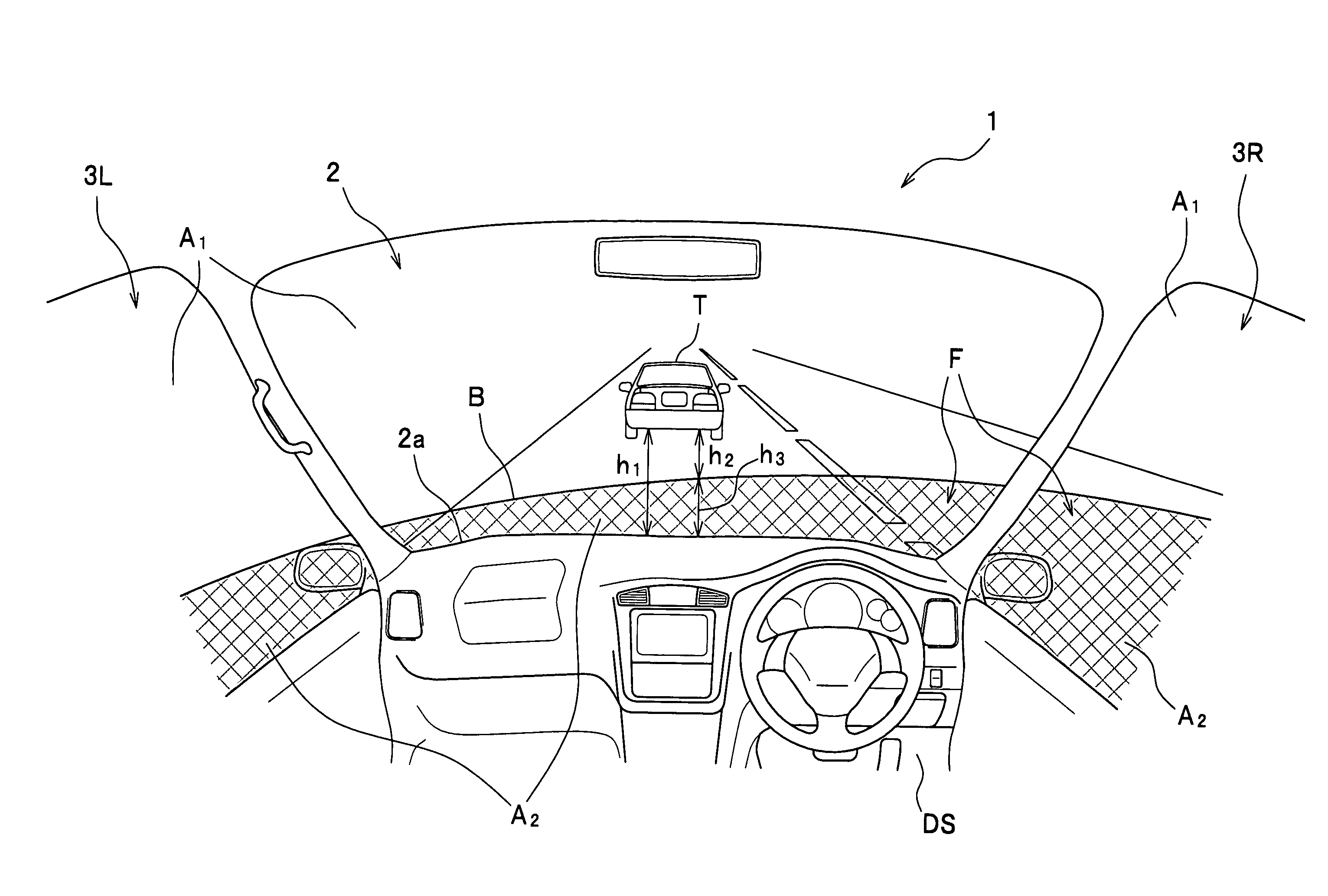
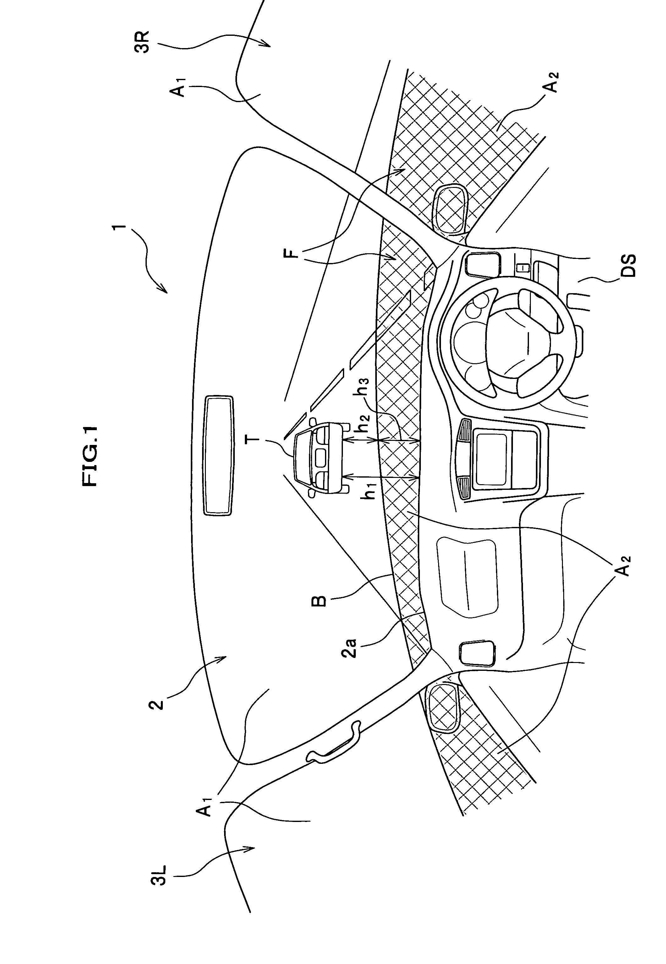
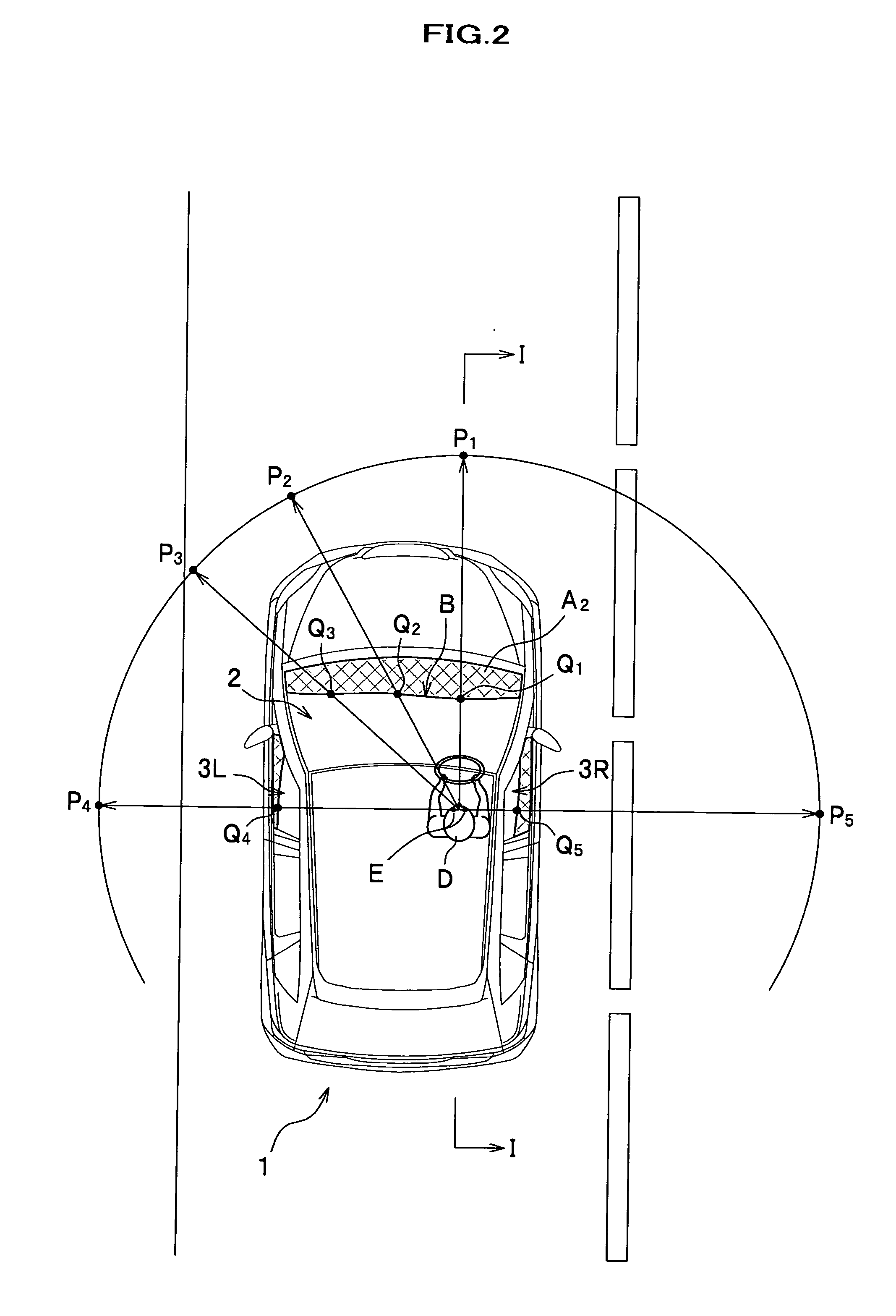
[0058]FIG. 1 is a drawing showing a front window and side windows of a vehicle related to a first embodiment of the present invention from a driver's view point. FIG. 2 is a plan view of the vehicle related to the first embodiment. FIG. 3 is an I-I section view of FIG. 2.

[0059] A vehicle 1 related to the first embodiment comprises, as shown in FIG. 1, one front window 2 and two side windows 3 (3L, 3R). Furthermore, a driver's seat DS related to the first embodiment is offset right with respect to the middle of the vehicle 1.

[0060] The front window 2 is a window made of glass provided before the driver's seat DS, and expresses a symmetrical shape with respect to the middle of the vehicle 1. In the first embodiment, as shown in FIG. 1, a second area A2 is formed by sticking a translucent film F on a lower area of the front window 2. In other words, the front window 2 is separated into a first area A1 of which a light transmission characteristic is not changed and the second area A2 ...

second embodiment

[0067]FIG. 4 is a drawing showing a front window and side windows of a vehicle related to a second embodiment of the present invention from a view point of a driver.

[0068] The vehicle 1 related to the second embodiment differs, as shown in FIG. 4, from the first embodiment in a point that the front window 2 and the side windows 3 are separated into the first area A1 and the second area A2 by providing a boundary line BL in the window 2 and the windows 3.

[0069] The front window 2 is, as shown in FIG. 4, separated into the first area A1 and the second area A2. Such the boundary line BL is provided along positions (symbol Q (Q1, Q2, . . . ) in FIGS. 2, 3) where the looking-down angle θ of the driver D is constant. Therefore, the driver D can accurately recognize points on a road face existing at an equal distance from herself / himself, making the boundary line BL a reference. Furthermore, because the interval h2 between the boundary line BL and the object T is smaller than the interva...

third embodiment

[0072]FIG. 5 is a drawing showing a front window and side windows of a vehicle related to a third embodiment of the present invention from a view point of a driver.

[0073]FIG. 6 is an illustration drawing showing a relationship between each boundary of a first area, a second area, and a third area, and driver's eyes. The vehicle 1 related to the third embodiment differs, as shown in FIG. 5, from the first and second embodiments in a point that the front window 2 and the side windows 3 are separated into three, the first area A1, the second area A2, and the third area A3.

[0074] In the front window 2 and the side windows 3 of the vehicle 1 related to the third embodiment, as shown in FIG. 5, the films F are stuck on an upper portion and lower portion thereof, and the third area A3 and the second area A2 are formed by the films F, respectively. Therefore, a size of the first area A1 becomes smaller, and an area change of the object T is felt larger with respect to the first area A1. T...


PUM


Abstract

The vehicle is equipped with a front window having a light transmission characteristic and separated into a first area and a second area provided below the first area, wherein a boundary between the first area and the second area is provided so that a looking-down angle from a driver is constant.

Description

BACKGROUND OF THE INVENTION [0001] 1. Field of the Invention [0002] The present invention relates to a vehicle, and more particularly, to a vehicle of which a recognition accuracy of visual information such as a following distance visually recognized by a driver is enhanced. [0003] 2. Description of the Related Art [0004] A driver of a vehicle recognizes an object such as another vehicle by vision, and performs a situational judgment and a driving operation. At this time, if scenery around is too seeable, driver's fatigue and drowsiness become strong in some case. Consequently, by restricting a part of a view according to a driving situation, it is performed that the driver's fatigue and drowsiness are prevented and that safety driving is ensured. [0005] For example, in Japanese Patent Laid-Open Publication No. 2000-211355 (paraphrases 0009 to 0016, FIG. 5) is disclosed a technology of: detecting such an actual vehicle speed and a following distance; and for example, in a case that ...

Claims


Application Information

Patent Timeline
Patent Type & Authority Applications(United States)
IPC IPC(8): B60J1/02
CPCB60J1/02B60J1/2011
Inventor UEMATSU, HIROSHIUEMATSU, ISAO
Owner HONDA MOTOR CO LTD
Why Eureka
Try Eureka