Vehicle for enhancing recognition accuracy of visual information
a technology for visual information and vehicles, applied in the field of vehicles, can solve the problems of increased confusion, increased fatigue and drowsiness of drivers, and incomplete blockage of requested information, and achieve the effect of enhanced recognition accuracy and no damage to safety
- Summary
- Abstract
- Description
- Claims
- Application Information
AI Technical Summary
Benefits of technology
Problems solved by technology
Method used
Image
Examples
first embodiment
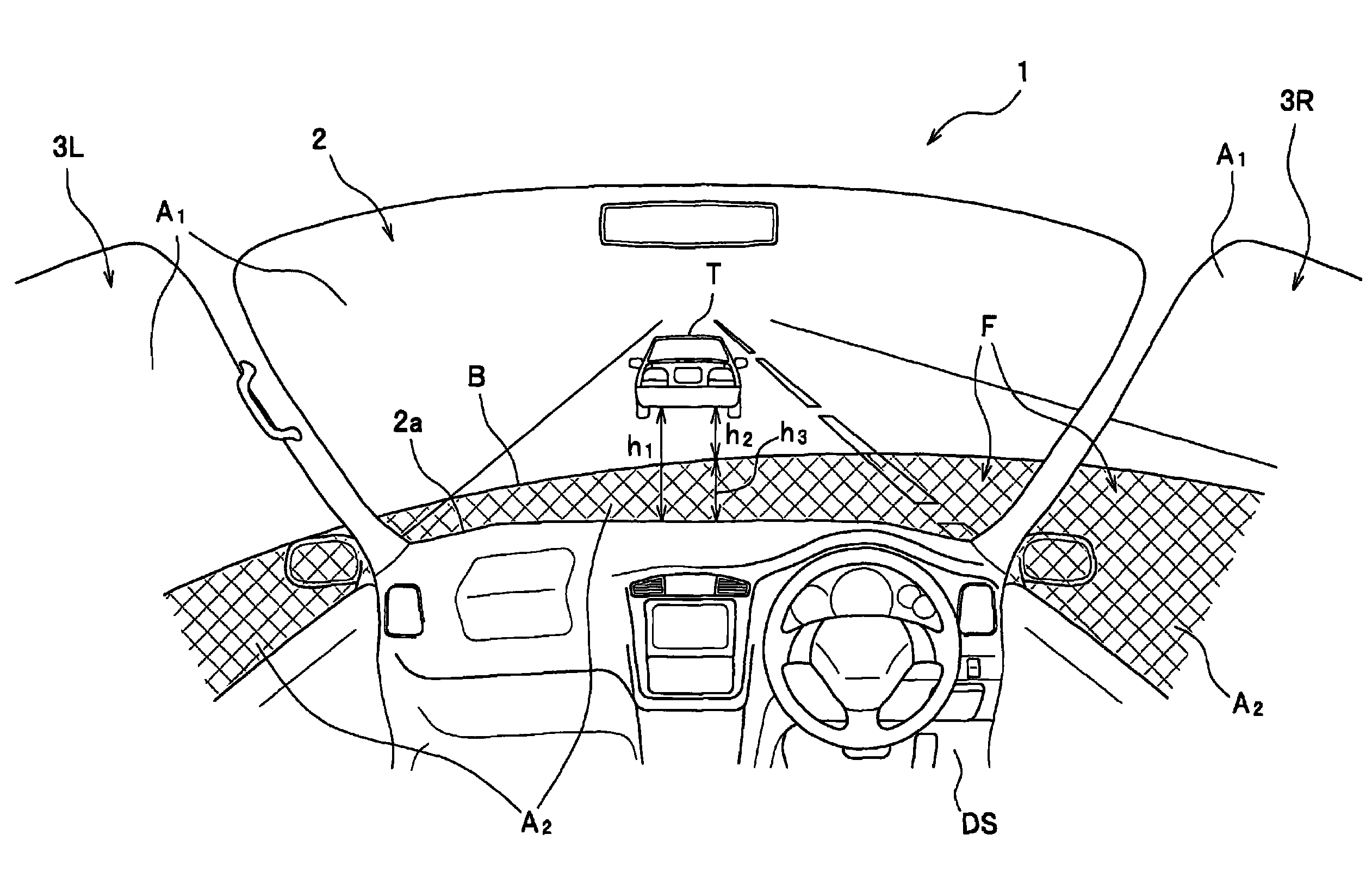
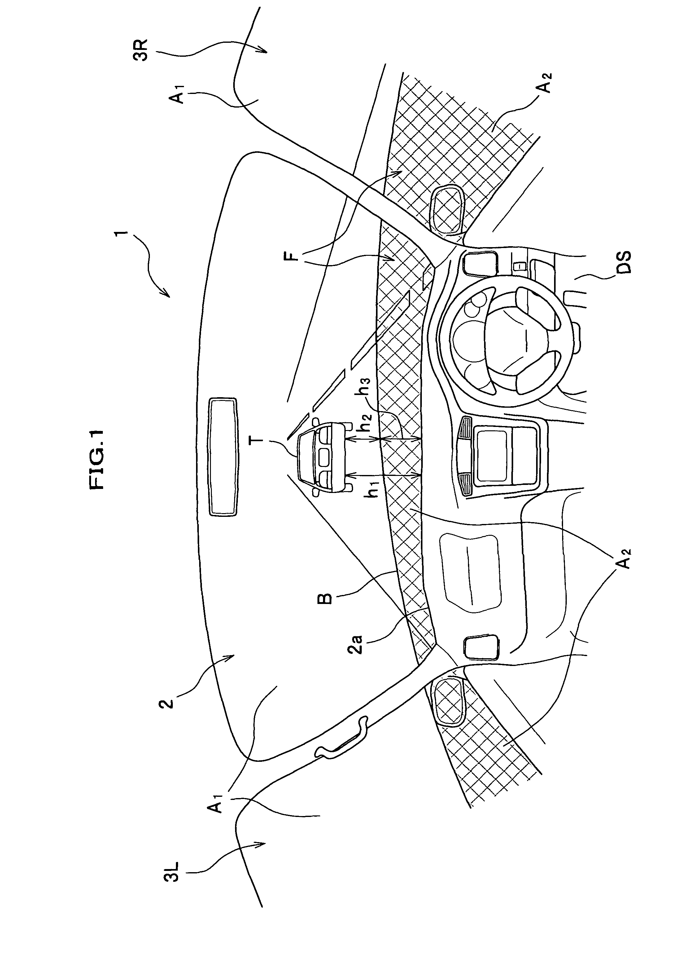
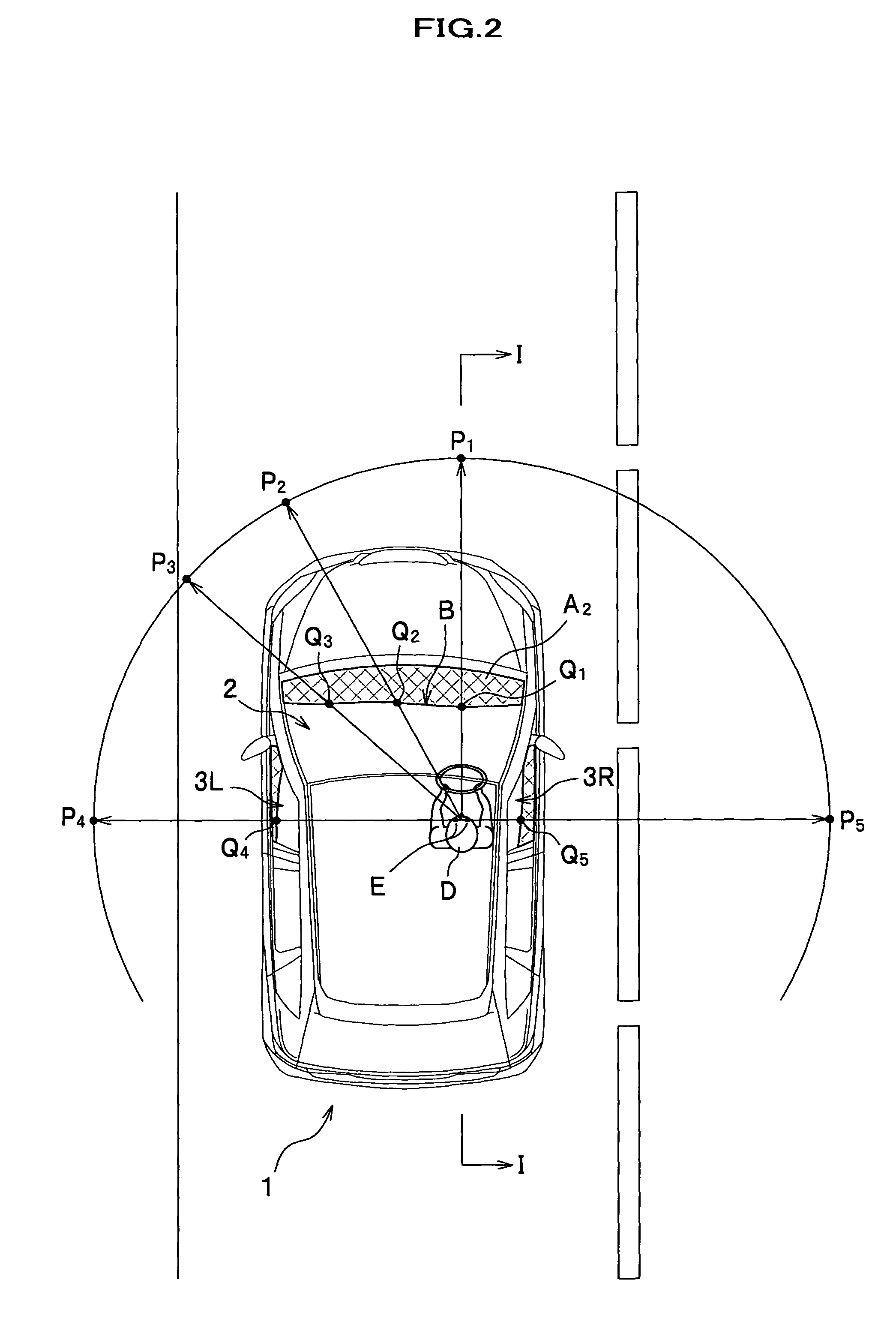
[0058]FIG. 1 is a drawing showing a front window and side windows of a vehicle related to a first embodiment of the present invention from a driver's view point. FIG. 2 is a plan view of the vehicle related to the first embodiment. FIG. 3 is an I-I section view of FIG. 2.
[0059]A vehicle 1 related to the first embodiment comprises, as shown in FIG. 1, one front window 2 and two side windows 3 (3L, 3R). Furthermore, a driver's seat DS related to the first embodiment is offset right with respect to the middle of the vehicle 1.
[0060]The front window 2 is a window made of glass provided before the driver's seat DS, and expresses a symmetrical shape with respect to the middle of the vehicle 1. In the first embodiment, as shown in FIG. 1, a second area A2 is formed by sticking a translucent film F on a lower area of the front window 2. In other words, the front window 2 is separated into a first area A1 of which a light transmission characteristic is not changed and the second area A2 of w...
second embodiment
[0067]FIG. 4 is a drawing showing a front window and side windows of a vehicle related to a second embodiment of the present invention from a view point of a driver.
[0068]The vehicle 1 related to the second embodiment differs, as shown in FIG. 4, from the first embodiment in a point that the front window 2 and the side windows 3 are separated into the first area A1 and the second area A2 by providing a boundary line BL in the window 2 and the windows 3.
[0069]The front window 2 is, as shown in FIG. 4, separated into the first area A1 and the second area A2. Such the boundary line BL is provided along positions (symbol Q (Q1, Q2, . . . ) in FIGS. 2, 3) where the looking-down angle θ of the driver D is constant. Therefore, the driver D can accurately recognize points on a road face existing at an equal distance from herself / himself, making the boundary line BL a reference. Furthermore, because the interval h2 between the boundary line BL and the object T is smaller than the interval h1...
third embodiment
[0072]FIG. 5 is a drawing showing a front window and side windows of a vehicle related to a third embodiment of the present invention from a view point of a driver.
[0073]FIG. 6 is an illustration drawing showing a relationship between each boundary of a first area, a second area, and a third area, and driver's eyes.
[0074]The vehicle 1 related to the third embodiment differs, as shown in FIG. 5, from the first and second embodiments in a point that the front window 2 and the side windows 3 are separated into three, the first area A1, the second area A2, and the third area A3.
[0075]In the front window 2 and the side windows 3 of the vehicle 1 related to the third embodiment, as shown in FIG. 5, the films F are stuck on an upper portion and lower portion thereof, and the third area A3 and the second area A2 are formed by the films F, respectively. Therefore, a size of the first area A1 becomes smaller, and an area change of the object T is felt larger with respect to the first area A1....
PUM
 Abstract
Description
Claims
Application Information
 - R&D
- Intellectual Property
- Life Sciences
- Materials
- Tech Scout
- Unparalleled Data Quality
- Higher Quality Content
- 60% Fewer Hallucinations
Browse by: Latest US Patents, China's latest patents, Technical Efficacy Thesaurus, Application Domain, Technology Topic, Popular Technical Reports.
© 2025 PatSnap. All rights reserved.Legal|Privacy policy|Modern Slavery Act Transparency Statement|Sitemap|About US| Contact US: help@patsnap.com


