Barrier identification method and system of laser radar

A technology of obstacle identification and laser radar, which is applied in radio wave measurement system, satellite radio beacon positioning system, electromagnetic wave reradiation, etc., can solve the problem of undetectable obstacle type, and achieve fast speed and high recognition accuracy Effect

Active Publication Date: 2018-06-12
SHANGHAI ALLYNAV TECH CO LTD
9 Cites 95 Cited by

AI-Extracted Technical Summary

Problems solved by technology

However, a large number of high-quality samples are required for training, and ...

Method used

3) to each frame multivariate point cloud data, use the translation and the rotation matrix that position and posture information provide, carry out the rigid body transformation of point cloud coordinate system, the point cloud relative global earth coordinate system that compensation pose change brings deviation. Through point cloud data space matching, the obtained fused point cloud data stream c...

Abstract

The invention provides a barrier identification method and system of a laser radar. The method comprises that S1) original point cloud data, position data and attitude data are fused to obtain fused point cloud data; S2) the fused point cloud data is divided into multiple fused point cloud data segments according to the time sequence, and ICP registering is carried out on point cloud in each fusedpoint cloud data segment to obtain superposed point cloud data; S3) point clouds of each group of superposed point cloud data segment are clustered to obtain candidate barriers, and static information of the candidate barriers is extracted; and S4) according to the static information of the candidate barriers, static and dynamic barriers are identified from the candidate barrier, and dynamic information of the dynamic barrier is extracted. A graph can be made needless of using offline data of the laser radar, the method and system are suitable for detecting barriers in different complex application environments, the identification precision is high, and the speed is high.

Application Domain

Technology Topic

Image

  • Barrier identification method and system of laser radar
  • Barrier identification method and system of laser radar
  • Barrier identification method and system of laser radar

Examples

  • Experimental program(1)

Example Embodiment

[0043] In order to make the objectives, technical solutions, and advantages of the embodiments of the present invention clearer, the following will clearly describe the technical solutions in the embodiments of the present invention with reference to the accompanying drawings in the embodiments of the present invention. Obviously, the described embodiments are the present invention. Invented some embodiments, but not all embodiments. Based on the embodiments of the present invention, all other embodiments obtained by those of ordinary skill in the art without creative work shall fall within the protection scope of the present invention.
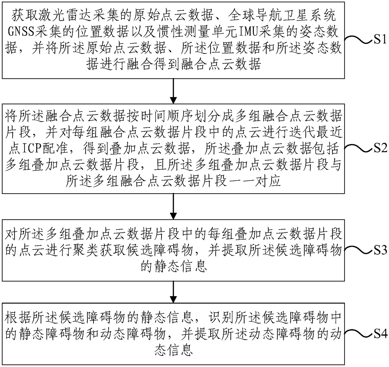
[0044] figure 1 This is a flowchart of a method for identifying obstacles in lidar provided by an embodiment of the present invention, such as figure 1 As shown, the method includes: S1, acquiring raw point cloud data collected by lidar, position data collected by a global navigation satellite system GNSS, and attitude data collected by an inertial measurement unit IMU, and combining the raw point cloud data with the The position data and the posture data are fused to obtain fused point cloud data; S2, the fused point cloud data is divided into multiple groups of fused point cloud data fragments in chronological order, and the point cloud in each group of fused point cloud data fragments Perform iterative closest point ICP registration to obtain superimposed point cloud data. The superimposed point cloud data includes multiple sets of superimposed point cloud data fragments, and the multiple sets of superimposed point cloud data fragments and the multiple sets of fused point cloud data fragments are one One correspondence; S3, clustering the point clouds of each of the multiple sets of overlapping point cloud data fragments to obtain candidate obstacles, and extracting static information of the candidate obstacles; S4, according to all The static information of the candidate obstacle is identified, the static obstacle and the dynamic obstacle in the candidate obstacle are identified, and the dynamic information of the dynamic obstacle is extracted.
[0045] Specifically, in step S1, the lidar, the global navigation satellite system (Global Navigation Satellite System, GNSS), and the inertial measurement unit (Inertial Measurement Unit, IMU) are all fixedly installed on a carrier, and the carrier is Different application scenarios can generally be robots, unmanned vehicles, or automated agricultural machinery.
[0046] Since each point cloud in the original point cloud data collected by lidar is not under the geodetic coordinate system, the position data collected by GNSS and the attitude data collected by the IMU are fused with the original point cloud data, and the original point cloud data can be integrated The point cloud is converted to the geodetic coordinate system to obtain the fusion point transportation data. The fusion point transport data can be directly used for fine registration in the subsequent point cloud ICP.
[0047] In step S2, when segmenting the fusion point cloud data by time, due to different application scenarios, the moving speed of obstacles in the environment will be different, and time segments of different frames should be used for segmentation.
[0048] When the moving speed of the dynamic obstacle in the scene is slow, the time segment with a larger number of frames is used to increase the space occupied by the point cloud of the dynamic obstacle in a single time segment, and the probability of missed recognition of the slow dynamic obstacle is reduced.
[0049] When the moving speed of the dynamic obstacle in the scene is faster, the time segment with a smaller number of frames is superimposed to reduce the space occupied by the dynamic obstacle point cloud in a single time segment, and reduce the mismatch probability of the fast dynamic obstacle.
[0050] For example, set the number of frames of 10, 5, and 2 frames, corresponding to the time segment length of 2s, 1s, and 0.4s respectively, to handle slow speed ( <0.5m/s), medium speed (0.5~1m/s), fast (> 1m/s) dynamic obstacles. It is also possible to initially adopt a 5-frame time segment, and then dynamically adjust the number of time-slice frames according to the maximum speed of the dynamic obstacle.
[0051] In step S3, the static information can be considered as an inherent attribute of the obstacle, and both dynamic obstacles and static obstacles contain static information.
[0052] In step S4, as long as the static obstacles or dynamic obstacles among the candidate obstacles are identified, the dynamic and static attributes of all obstacles of the candidate obstacles can be distinguished, so that the identification of the obstacles is more accurate.
[0053] According to an embodiment of the present invention, a lidar obstacle recognition method is used to obtain fused point cloud data by fusing original point cloud data using position data and posture data, and then divide the fused point cloud data into multiple fragments according to time, and The point cloud in each segment is registered, and dynamic and static obstacles are identified from the superimposed point cloud data obtained after registration. There is no need to use lidar offline data to build maps, and it is suitable for obstacle detection in various complex application environments, with high recognition accuracy and fast speed.
[0054] Based on the foregoing embodiment, step S1 specifically includes:
[0055] The original point cloud data and the posture data are down-sampled so that the frequencies of the original point cloud data, the position data and the posture data are the same, and each of the original point cloud data is One frame of point cloud corresponds to one position and one posture; wherein, the original point cloud data, the position data and the posture data constitute a multivariate point cloud data set;
[0056] Obtain the previous frame of point cloud of each frame of point cloud according to the corresponding position and posture of each frame of point cloud and the previous frame of point cloud of each frame of point cloud in the multivariate point cloud data set Transform to the first translation matrix and the first rotation matrix corresponding to each frame of point cloud;
[0057] Using the first translation matrix and the first rotation matrix, the point cloud of each frame is converted to a geodetic coordinate system to obtain the fused point cloud data.
[0058] Specifically, the original point cloud data, the position data, and the posture data are fused, that is, the original point cloud data and the pose data are matched in time and space.
[0059] For example, if the frequency of the original point cloud data collected by the 3D lidar is 10 Hz, the frequency of the position data collected by the GNSS is 5 Hz, and the frequency of the attitude data collected by the IMU is 100 Hz. Each sensor has a different collection period, so the data needs to be time matched. The specific steps are as follows:
[0060] 1) Lidar point cloud data: The scanning frequency of 3D Lidar is 10Hz. Through the method of inter-frame sampling, only the odd-numbered frame point cloud data of the radar is retained, and even-numbered frames are discarded, and the point cloud data frequency is reduced to 5Hz.
[0061] 2) GNSS data: GNSS is carrier phase differential positioning, with centimeter-level positioning accuracy, and the typical solution frequency for fixed solutions is 5Hz.
[0062] 3) IMU data: IMU provides high frequency (> 100Hz) attitude data. The original posture data is sampled at equal intervals for filtering (mean filter, median filter, etc.), and the posture data is reduced to 5 Hz.
[0063] 4) Correspondingly correlate the information of the elapsed time matching to construct a "point cloud-position-posture" multi-point cloud data stream (5 Hz) as a multi-point cloud data set for spatial matching of point cloud data.
[0064] Detecting obstacle information requires high-precision registration of the original point cloud. The point cloud registration is divided into coarse registration and fine registration according to the accuracy. Coarse registration has lower requirements for the initial pose of the original data, but the error is larger. The precision registration error is small, but the original data is required to have good pose consistency. For mobile acquisition platforms such as unmanned vehicles and robots, their movement causes the coordinate system of the point cloud data centered on the lidar to produce translation and rotation changes, and it is difficult to meet the requirements of precise registration by directly using the original point cloud.
[0065] Further spatial matching is performed on the "point cloud-position-posture" multivariate point cloud data stream that has been matched over time, that is, the translation matrix is ​​determined by the differential position information of GNSS, the rotation matrix is ​​determined by the posture information of IMU, and the initial pose of the point cloud is performed Estimated as the initial pose estimation for ICP fine registration.
[0066] 1) Obtain the GPGGA sentence of NMEA through the carrier phase differential positioning signal of GNSS, and extract the current longitude, latitude, and altitude information. Through projection and coordinate transformation, the position of the car body can be obtained stably and accurately, that is, the position of the lidar in the geodetic coordinate system, and then the translation matrix in the two-frame point cloud coordinate transformation can be obtained.
[0067] 2) Through the accelerometer, gyroscope, magnetic deflection meter (only AHRS equipped) on the IMU, the internal Kalman filter, complementary filtering and other methods are used for data fusion, and the vehicle body attitude information (roll angle, pitch angle, Heading angle), and then obtain the rotation matrix (Eulerian angle or quaternion) in the two-frame point cloud coordinate transformation.
[0068] 3) For each frame of multi-element point cloud data, use the translation and rotation matrix provided by the position and attitude information to perform the rigid body transformation of the point cloud coordinate system to compensate for the deviation of the point cloud from the global geodetic coordinate system caused by the pose change. Through spatial matching of point cloud data, the obtained fused point cloud data stream can provide accurate and reliable pose information for ICP registration, thereby improving the accuracy of ICP registration, reducing the number of iterations, and enhancing real-time performance.
[0069] Based on the foregoing embodiment, the method further includes:
[0070] After the original point cloud data, the position data, and the posture data are fused to obtain the first fused point cloud data, the first fused point cloud data that exceeds a preset radius and is below the preset radius are filtered out respectively High point cloud to obtain the second fusion point cloud data;
[0071] Filter out any three adjacent point clouds whose connection curvature exceeds a preset threshold in the second fusion data to obtain the fusion point cloud data.
[0072] Specifically, the point cloud exceeding a certain distance has a low correlation with the current obstacle detection, and a large number of weakly correlated point clouds will affect the accuracy of registration. Ground points will cause great interference to point cloud matching and obstacle detection: Lidar scan lines have a high similarity on the horizontal ground, and the ICP algorithm may fall into a local minimum. The point cloud on the slope road may be recognized as an obstacle due to its high height.
[0073] 1) Point cloud range trimming: Limit the collection range of lidar. For example, only point clouds within 50m (according to actual conditions) can be considered to reduce weakly correlated point cloud data.
[0074] 2) Ground point cloud filtering: Determine the approximate ground range according to the vehicle body information and the relative position of the vehicle body and the radar installation (rigid body transformation), and filter out the ground points by filtering the data height and curvature information within the threshold. The specific method is as follows:
[0075] The lidar is fixed horizontally on the top of the mobile platform. According to the rotation scanning parameters of the 3D lidar (the vertical angle of the scan line), combined with the installation height of the radar on the vehicle body, the height threshold and the neighboring point cloud curvature threshold are used as features, and the height will be lower than the height The threshold point cloud (flat spot cloud) and the point cloud (slope point cloud) whose curvature approximates a smooth circle at the neighboring points are regarded as ground point clouds, and filtered and removed.
[0076] In addition, in the specific implementation, the following methods can also be used to filter the ground point cloud: plane fitting the point cloud data to obtain the plane information in the scene, which is expected to include flat place cloud, slope point cloud and wall Facade point cloud etc. Then calculate the angle between these fitting planes and the horizontal reference surface (provided by AHRS/IMU), take the point cloud within the preset angle range as the point cloud to be filtered, and perform filtering. Among them, the preset angle range can be determined by the actual climbing ability of the vehicle body.
[0077] Point cloud clipping and filtering can reduce interference, and at the same time reduce the amount of point cloud data, which can improve the efficiency of point cloud matching and feature extraction to a certain extent.
[0078] Based on the foregoing embodiment, in step S2, the iterative closest point ICP registration is performed on the point clouds in each group of fused point cloud data fragments to obtain superimposed point cloud data, which specifically includes:
[0079] S21, taking the first frame point cloud in each group of fused point cloud data fragments as the first source point cloud and the second frame point cloud as the first target point cloud, and comparing the first source point cloud and the first point cloud Perform ICP registration on a target point cloud to obtain the first registration point cloud;
[0080] S22: Using the first registration point cloud as the second source point cloud and the third frame point cloud as the second target point cloud, perform ICP registration on the second source point cloud and the second target point cloud to obtain For the second point cloud registration, the above-mentioned registration operation is repeated until the registration of all the point clouds in each group of fused point cloud data segments is completed, and the superimposed point cloud data is obtained.
[0081] Based on the foregoing embodiment, step S21 specifically includes:
[0082] The second translation matrix and the second rotation matrix between the first source point cloud and the first target point cloud are obtained through multiple iterations, and the second translation matrix and the second rotation matrix make the first The error between the source point cloud and the first target point cloud is the smallest;
[0083] Use the second translation matrix and the second rotation matrix to convert the first source point cloud to the coordinate system of the first target point cloud, and to convert to the coordinates of the first target point cloud The first source point cloud and the first target point cloud under the system are merged to obtain the first registration point cloud.
[0084] Specifically, such as figure 2 As shown, the stepwise ICP point cloud registration is performed on the N-frame fusion point cloud in each time slice. The specific method is as follows:
[0085] 1) Record the N-frame fusion point cloud in each time slice as C 1 ~C N
[0086] 2) Put C 1 As the source point cloud, C 2 As the target point cloud, the point cloud to be registered as the ICP 3) Extract the feature information of the target point cloud and the source point cloud, and use the weighted as the error factor 4) Perform the least square error calculation on the target point cloud and the source point cloud, such as Find the rotation matrix R and the translation matrix T that meet the conditions, so that the error is less than the threshold, then jump to 5), otherwise repeat 4). If the number of iterations reaches the threshold of the maximum number of iterations, jump to 5).
[0087] 5) Perform a rigid body transformation composed of a rotation matrix and a translation vector on the source point cloud, and convert its point cloud coordinates to the target point cloud coordinate system. The source point cloud and the target point cloud are merged and recorded as a matched point cloud.
[0088] 6) If all N frames of point clouds are registered, go to 7), otherwise the point cloud to be matched in the next frame is the target point cloud, and the matched partial point cloud subset is the source point cloud, go to 3).
[0089] 7) The point cloud registration of N frames in the time slice is completed, and the superimposed point cloud in this time slice is obtained.
[0090] The details of the time slice overlay registration method are as follows:
[0091] The initial pose estimation is critical to the ICP fine registration method, which directly affects its registration accuracy and speed. Since GNSS is used to provide accurate position and AHRS/IMU provides reliable attitude, the point cloud to be registered has been spatially registered in the preprocessing stage, so the default transformation matrix for initial pose estimation is the 4th order identity matrix, which means it is no longer needed Make a transformation.
[0092] The error factor in point cloud registration is weighted with a certain weight (such as 1:1:1:1:1) based on the spatial coordinates X, Y, Z, point cloud reflectivity, and point cloud normal direction information. Among them, the first three are spatial attributes, reflectivity is the material attribute, and the normal direction is the regional attribute, which has good fusion.
[0093] Based on the foregoing embodiment, step S3 specifically includes:
[0094] Use the superbody clustering algorithm to cluster the point clouds in each group of superimposed point cloud data fragments to obtain the candidate obstacles corresponding to each group of superimposed point cloud data fragments, and extract the candidate obstacles corresponding to each group of superimposed point cloud data fragments Static information, the static information includes at least the center of mass, inner and outer contours, volume, average reflectivity and average point cloud density.
[0095] Specifically, cluster the superimposed fusion point clouds of each time slice after registration, divide obstacle blocks, and extract static information of obstacles such as centroid, inner and outer contours, volume, average reflectivity, and average point cloud density. The inner and outer contours can be cuboid, cylinder or sphere.
[0096] 1) According to the superbody clustering method, cluster a subset of local point clouds to obtain candidate obstacles.
[0097] The concept of super voxel comes from image segmentation. In the field of 3D point cloud, super voxel is a region growing clustering method after segmentation of the point cloud, which is a bottom-up induction method. Superbody clustering first performs octree segmentation on the point cloud data, distributes "voxel seeds" in the octree, and sets parameters such as "voxel distance" and "minimum voxel". In the process of voxel merging, small voxels are gradually merged into nearby large voxels to realize point cloud clustering.
[0098] In actual implementation, K-means method, maximum likelihood method or fuzzy clustering method can also be used to obtain candidate obstacles.
[0099] 2) Perform feature extraction on candidate obstacles, and extract parameters such as centroid, inner and outer contours, volume, average reflectivity, and average point cloud density. The specific method is as follows:
[0100] Centroid: The point cloud block is regarded as a homogeneous body, so the centroid is the geometric center of the point cloud, which is obtained by averaging the XYZ coordinates of the point cloud.
[0101] Outer contour: filter the discrete points of the point cloud block, remove outliers, and extract the outer contour of the circumscribed cuboid, cylinder, and sphere.
[0102] Inner contour: The inner contour is determined based on the outer contour, which contains 90% (according to the actual situation) of the same type contour of the total point cloud.
[0103] Volume: Take the volume of the inner contour geometry as the point cloud volume.
[0104] Average reflectivity: It is characterized by the average reflectivity of all point clouds in the point cloud block.
[0105] Average point cloud density: It is characterized by the ratio of the number of point clouds to the volume in the inner contour of the point cloud block.
[0106] 3) Establish a linked list of obstacles to store static information of obstacles (centroid, inner and outer contours, volume, average reflectivity, average point cloud density).
[0107] Based on the foregoing embodiment, step S4 specifically includes:
[0108] For each candidate obstacle in the candidate obstacles corresponding to each set of superimposed point cloud data fragments, each candidate is constructed with the centroid, inner and outer contours, volume, average reflectivity and average point cloud density of each candidate obstacle as characteristic components Feature vectors of obstacles, and perform cross-correlation analysis on each candidate obstacle and the candidate obstacles corresponding to the adjacent overlapping point cloud data fragments to obtain each candidate obstacle and the adjacent overlapping point cloud data fragments The correlation number between each obstacle in the corresponding candidate obstacle.
[0109] among them:
[0110] ① The centroid component is the space coordinate of the centroid (X, Y, Z);
[0111] ②The inner and outer contour components are typical contour shapes (cube, cylinder, sphere, etc.);
[0112] ③The volume component is the size of the point cloud and its aspect ratio;
[0113] ④The average emissivity component is 256-level quantized reflectivity;
[0114] ⑤The average point cloud density component is the number of point clouds per unit volume in the inner contour.
[0115] For any candidate obstacle among the candidate obstacles corresponding to each group of superimposed point cloud data fragments, the candidate obstacles corresponding to the adjacent superimposed point cloud data fragments are mutually The candidate obstacles whose relationship number is greater than the preset threshold are regarded as the same obstacle of any candidate obstacle.
[0116] In particular:
[0117] ① If the same obstacle has multiple paired obstacles whose correlation coefficient is greater than the threshold, the one with the largest value is the first paired obstacle. If there is an obstacle matching conflict, take the mutual relationship value as the criterion, keep the current highest pair of mutual relationship, and eliminate the mutually exclusive pair. Repeat the above process until the obstacle pairing is completed;
[0118] ②If the correlation coefficient between an obstacle and other obstacles in the previous set of superimposed point clouds is less than the threshold, it is judged as the disappearing obstacle;
[0119] ③If the correlation coefficients between an obstacle and other obstacles in the latter group of superimposed point clouds are all less than the threshold, it is judged as a new obstacle.
[0120] Compare the centroid positions of the same obstacle in the two sets of adjacent superimposed point cloud data fragments, identify the same obstacle whose centroid position has changed as a dynamic obstacle, and extract the dynamic information of the dynamic obstacle. The information includes at least speed and direction of movement.
[0121] Specifically, an obstacle whose position change amount of the center of mass does not exceed the first preset threshold is identified as a static obstacle and only has a static feature. Obstacles whose positional change of the centroid exceeds the first preset threshold are identified as dynamic obstacles and have static and dynamic characteristics. The movement speed and direction of the dynamic characteristics provide the basis for dynamic obstacle avoidance. At the same time, the method dynamically adjusts the number of frames of each group of superimposed point clouds according to the maximum obstacle speed to adapt to different environments.
[0122] Specifically, the superimposed point clouds of two adjacent time slices are compared to distinguish the environmental background from static obstacles and dynamic obstacles.
[0123] 1) The coordinate system of the point cloud subset after each group of point clouds is matched is consistent with the coordinate system of the point cloud of the Nth frame. Therefore, the time interval between each adjacent two sets of point cloud subsets is 0.2*N seconds.
[0124] 2) By fusing and superimposing the pose information of the Nth frame in the point cloud for two consecutive time slices, the rigid body transformation matrix can be obtained, and the two sets of maps can be converted to the same coordinate system using the rigid body transformation.
[0125] 3) According to the principle of similar matching, the obstacles are matched to form a linked list of obstacle pairs.
[0126] 4) Calculate the center movement speed of the associated obstacle pair, distinguish the dynamic and static properties of the obstacle, and estimate the speed vector of the dynamic obstacle.
[0127] 5) Output the dynamic and static attributes, position, size, speed (dynamic) and other information of the obstacle according to the obstacle pair linked list.
[0128] image 3 It is a structural block diagram of a lidar obstacle recognition system provided by an embodiment of the present invention, such as image 3 As shown, the system includes a data fusion module 1, a point cloud registration module 2, a clustering module 3, and a dynamic and static obstacle recognition module 4. among them:
[0129] The data fusion module 1 is used to obtain the original point cloud data collected by lidar, the position data collected by the global navigation satellite system GNSS, and the attitude data collected by the inertial measurement unit IMU, and combine the original point cloud data, the position data and the position data. The pose data is fused to obtain fused point cloud data. The point cloud registration module 2 is used to divide the fused point cloud data into multiple groups of fused point cloud data fragments in chronological order, and iteratively perform the closest point ICP registration on the point clouds in each group of fused point cloud data fragments to obtain The superimposed point cloud data includes multiple sets of superimposed point cloud data fragments, and the multiple sets of superimposed point cloud data fragments correspond to the multiple sets of fused point cloud data fragments one to one. The clustering module 3 is configured to cluster the point clouds of each of the multiple sets of superimposed point cloud data fragments to obtain candidate obstacles, and extract static information of the candidate obstacles. The dynamic and static obstacle recognition module 4 is configured to identify static obstacles and dynamic obstacles in the candidate obstacles according to the static information of the candidate obstacles, and extract the dynamic information of the dynamic obstacles.
[0130] The embodiment of the present invention discloses a computer program product. The computer program product includes a computer program stored on a non-transitory computer-readable storage medium. The computer program includes program instructions. When the program instructions are executed by a computer, The computer can execute the methods provided by the foregoing method embodiments, for example, including: obtaining the original point cloud data collected by lidar, the position data collected by the global navigation satellite system GNSS, and the attitude data collected by the inertial measurement unit IMU, and combining The point cloud data, the position data, and the posture data are fused to obtain fused point cloud data; the fused point cloud data is divided into groups of fused point cloud data fragments in chronological order, and each group of fused point cloud data fragments The point cloud in the iterative closest point ICP registration is performed to obtain superimposed point cloud data. The superimposed point cloud data includes multiple sets of superimposed point cloud data fragments, and the multiple sets of superimposed point cloud data fragments and the multiple sets of fusion points One-to-one correspondence of cloud data fragments; clustering the point clouds of each of the multiple sets of superimposed point cloud data fragments to obtain candidate obstacles, and extract the static information of the candidate obstacles; The static information of the candidate obstacle is identified, the static obstacle and the dynamic obstacle in the candidate obstacle are identified, and the dynamic information of the dynamic obstacle is extracted.
[0131] Embodiments of the present invention provide a non-transitory computer-readable storage medium that stores computer instructions that cause the computer to execute the methods provided in the foregoing method embodiments, such as Including: acquiring the original point cloud data collected by lidar, the position data collected by the global navigation satellite system GNSS, and the attitude data collected by the inertial measurement unit IMU, and performing the processing of the original point cloud data, the position data and the attitude data Fusion to obtain fused point cloud data; divide the fused point cloud data into multiple sets of fused point cloud data fragments in chronological order, and perform iterative closest point ICP registration to the point clouds in each set of fused point cloud data fragments to obtain an overlay Point cloud data, where the superimposed point cloud data includes multiple sets of superimposed point cloud data fragments, and the multiple sets of superimposed point cloud data fragments correspond to the multiple sets of fused point cloud data fragments in a one-to-one correspondence; Each group of cloud data fragments superimposed on the point cloud of the point cloud data fragments is clustered to obtain candidate obstacles, and the static information of the candidate obstacles is extracted; the candidate obstacles are identified according to the static information of the candidate obstacles Static obstacles and dynamic obstacles in, and extract the dynamic information of the dynamic obstacles.
[0132] A person of ordinary skill in the art can understand that all or part of the steps in the above method embodiments can be implemented by a program instructing relevant hardware. The foregoing program can be stored in a computer readable storage medium. When the program is executed, the program is executed. Including the steps of the foregoing method embodiment; and the foregoing storage medium includes: ROM, RAM, magnetic disk, or optical disk and other media that can store program codes.
[0133] Through the description of the above implementation manners, those skilled in the art can clearly understand that each implementation manner can be implemented by software plus a necessary general hardware platform, and of course, it can also be implemented by hardware. Based on this understanding, the above technical solution essentially or the part that contributes to the existing technology can be embodied in the form of a software product, and the computer software product can be stored in a computer-readable storage medium, such as ROM/RAM, magnetic A disc, an optical disc, etc., include a number of instructions to make a computer device (which may be a personal computer, a server, or a network device, etc.) execute the methods described in each embodiment or some parts of the embodiment.
[0134] Finally, it should be noted that the above embodiments are only used to illustrate the technical solutions of the present invention, not to limit it; although the present invention has been described in detail with reference to the foregoing embodiments, those of ordinary skill in the art should understand that: The technical solutions recorded in the foregoing embodiments are modified, or some of the technical features are equivalently replaced; these modifications or replacements do not cause the essence of the corresponding technical solutions to deviate from the spirit and scope of the technical solutions of the embodiments of the present invention.

PUM

no PUM

Description & Claims & Application Information

We can also present the details of the Description, Claims and Application information to help users get a comprehensive understanding of the technical details of the patent, such as background art, summary of invention, brief description of drawings, description of embodiments, and other original content. On the other hand, users can also determine the specific scope of protection of the technology through the list of claims; as well as understand the changes in the life cycle of the technology with the presentation of the patent timeline. Login to view more.

Similar technology patents

Video face identification algorithm on basis of multi-instance learning

ActiveCN104778457AImprove recognition accuracyAvoid difficult choicesCharacter and pattern recognitionInstance-based learningCharacteristic space
Owner:JILIN UNIV

Classification and recommendation of technical efficacy words

  • Improve recognition accuracy
  • Accelerate

People also interested in

Why Eureka
Try Eureka