
Tissue clamp

a technology of tissue clamps and clamps, which is applied in the field of tissue clamps, can solve problems such as difficulty in securely holding clamps, and achieve the effect of preventing premature release of clamps during placemen

Inactive Publication Date: 2007-05-10
UNIV OF MASSACHUSETTS
View PDF93 Cites 119 Cited by
  • Summary
  • Abstract
  • Description
  • Claims
  • Application Information

AI Technical Summary

Benefits of technology

The present invention is a system and method for clamping tissue, such as an artery, with a tissue clamp. The clamp has a fixture or peg that protrudes from the proximal end, which allows for easy placement and secure clamping. A tool engages the fixture to prevent premature release of the clamp. The tool and fixture can be rotated to select the desired rotational orientation. The technical effect of this invention is improved precision and ease of use when clamping tissue.

Problems solved by technology

The technical problem addressed in this patent text is the need for improvements in the operation of vascular clamps to improve safety and ease of use. Current forceps used to hold clamps are difficult to securely hold and may slip out during use, which can compromise the surgical procedure. There is a need for better tools to manipulate and stably apply clamps to blood vessels.

Method used


Image

  • Tissue clamp
  • Tissue clamp
  • Tissue clamp

Examples


Embodiment Construction

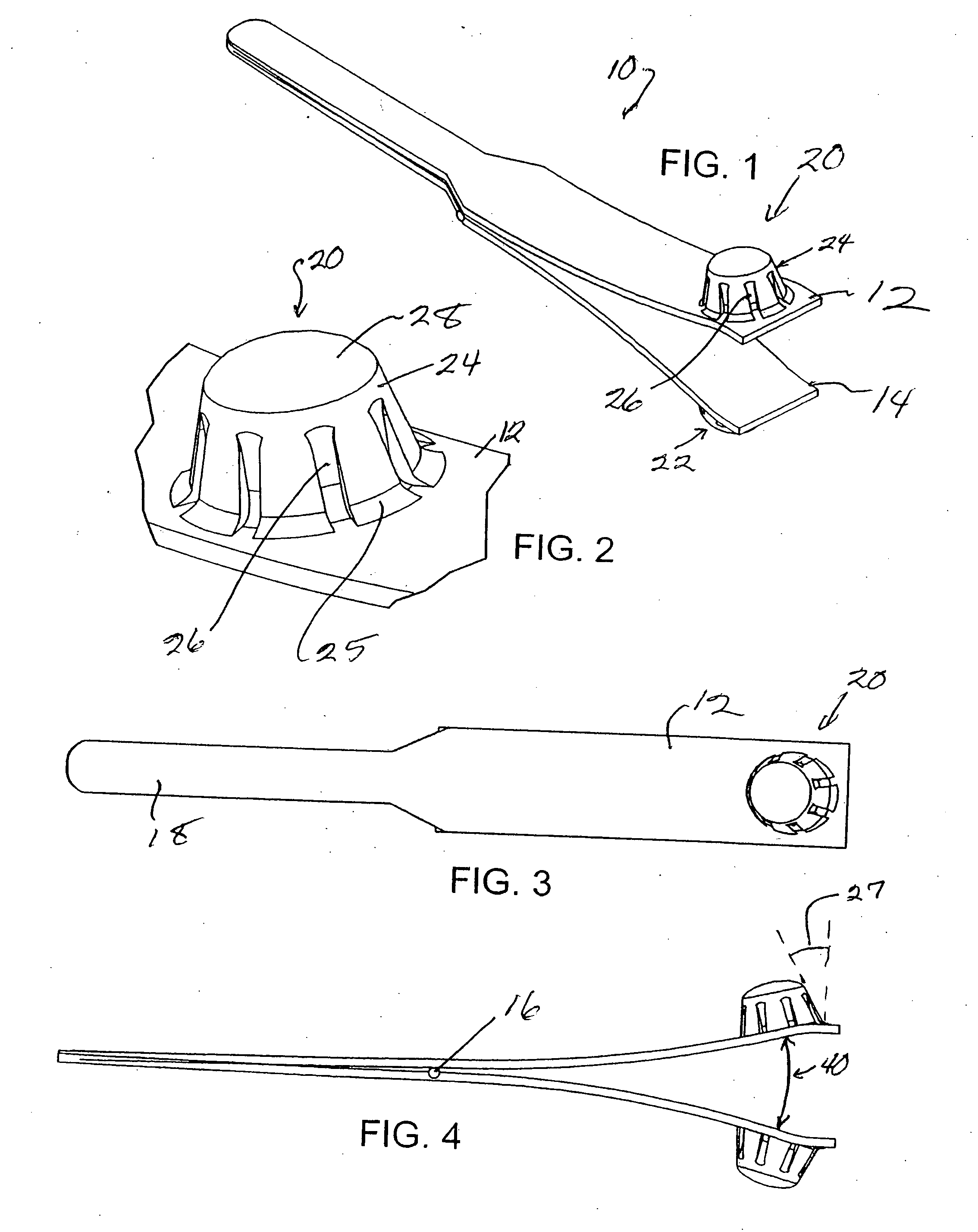
[0023] Illustrated in FIGS. 1-4 is a vascular clamp 10 having a fixture 20 on an arm 12 of the clamp that allows the clamp to be grasped by a tool that can be used by a surgeon, for example, to securely grasp and place the clamp during a surgical procedure. A preferred embodiment uses a second fixture 22 on the second arm 14 of the clamp so that a tool can securely grasp both arms.

[0024] The clamp is preferably used with a tool having elements that grasp fixtures 20, 22 and press the proximal ends of arms 12, 14 together to open the distal ends 18. The clamp is then positioned in proximity to a surgical site such that the open distal ends of arms 12, 14 can be positioned on opposite sides of an artery to be clamped. The surgeon then releases pressure exerted by the tool on the proximal ends of the arms of the clamp thereby allowing the distal ends to grasp and occlude the artery. This prevents blood flow to the surgical site such as a location for a graft, which can then be sutured...


PUM


Abstract

The present invention relates to a tissue clamp, a tool for grasping the clamp and a method of using the clamp for surgical procedures. The clamp has a fixture or fixtures positioned on the proximal end of the arms of the clamp so that a tool can be used by the surgeon to securely grasp the clamp during placement thereof on the vasculature or other tissue of the patient. The fixture can have a plurality of channels so that the user can select the angular orientation of the tool relative to the damp.

Description


Claims


Application Information

Patent Timeline
Owner UNIV OF MASSACHUSETTS
Features
  • Generate Ideas
  • Intellectual Property
  • Life Sciences
  • Materials
  • Tech Scout
  • Unparalleled Data Quality
  • Higher Quality Content
  • 60% Fewer Hallucinations
Learn More