Lap tray

a technology of trays and trays, applied in the field of trays, can solve the problem of not teaching a tray that is adapted for being positioned on the user's

Inactive Publication Date: 2007-05-24
LILLY CAROL W
View PDF27 Cites 33 Cited by
  • Summary
  • Abstract
  • Description
  • Claims
  • Application Information

AI Technical Summary

Problems solved by technology

However, the prior art does not teach a tray that is adapted for bein

Method used


Image

  • Lap tray
  • Lap tray
  • Lap tray

Examples


Embodiment Construction

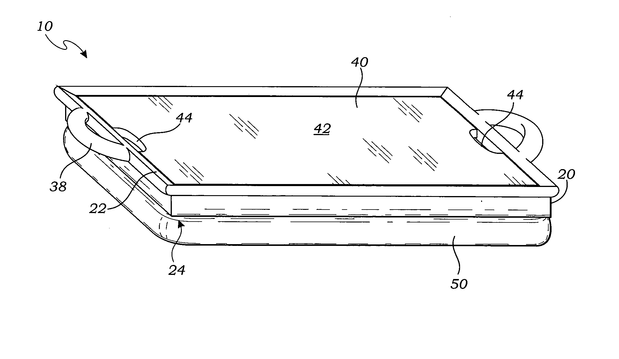
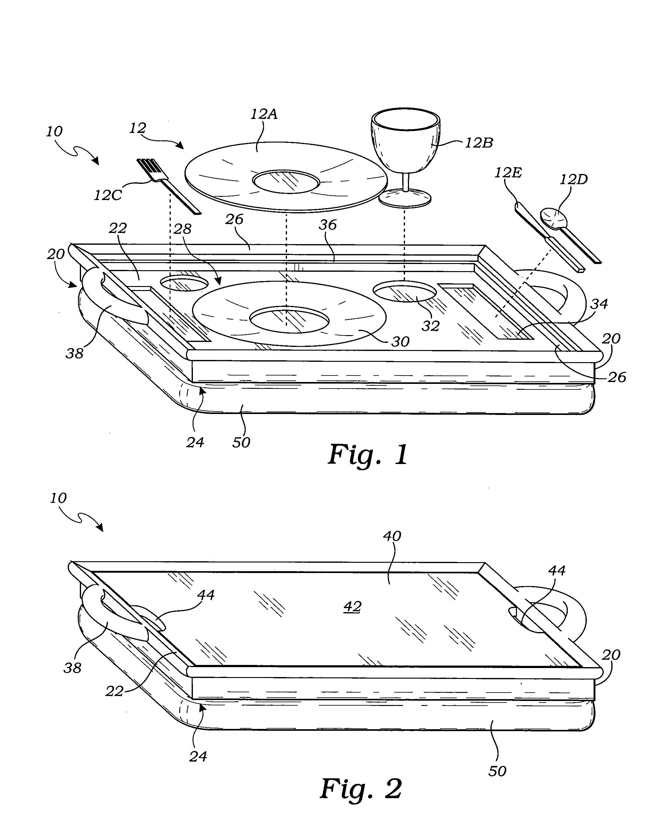
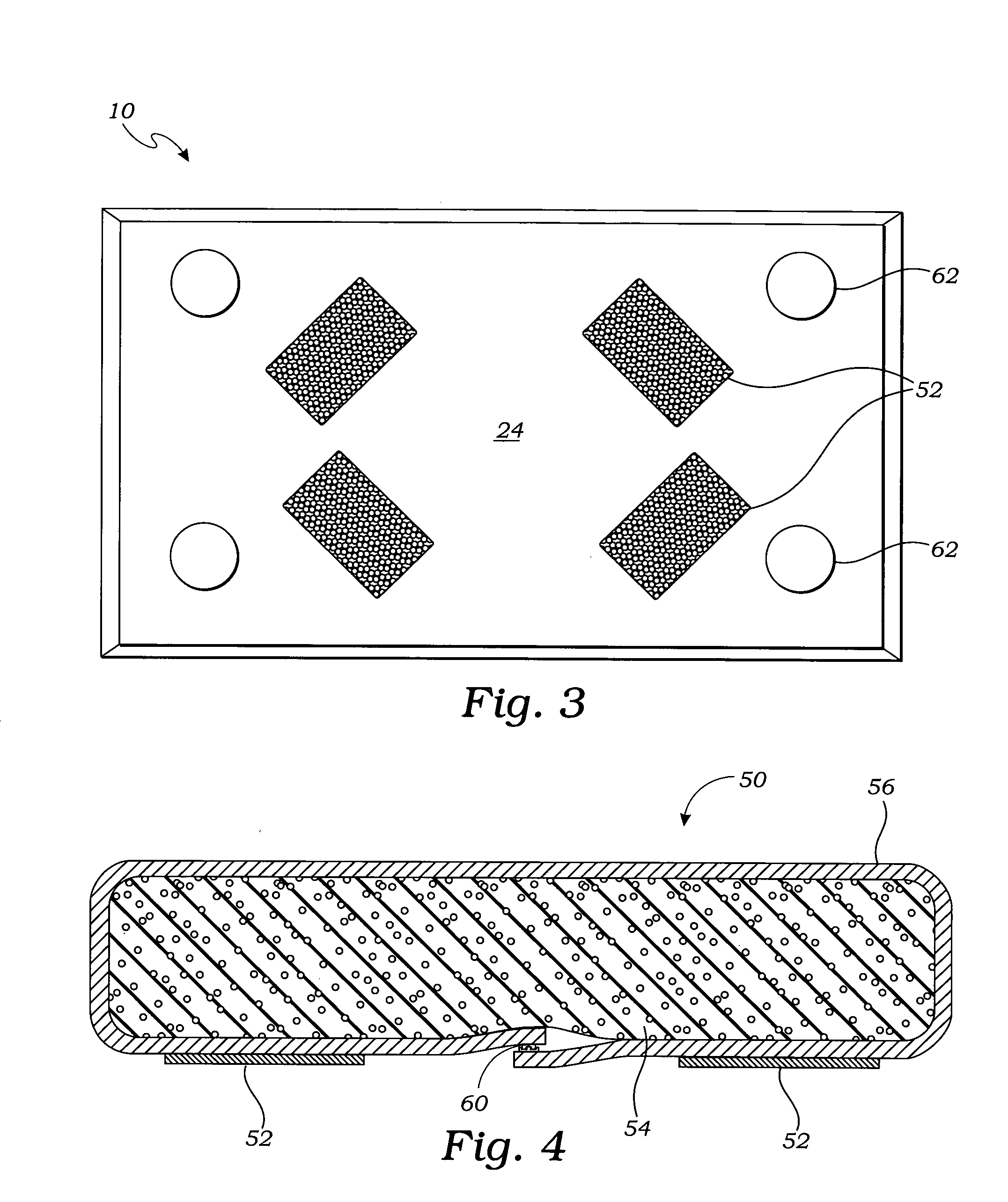
[0035] The above-described drawing figures illustrate the invention, a lap tray 10 for holding a plurality of eating utensils 12, or, alternatively, for providing a writing surface 42. Briefly stated, the lap tray 10 includes has a rigid base 20, a plurality of depressions 28, a cover element 40, and a lap pillow 50. As described in greater detail below, the plurality of depressions 28 hold the plurality of eating utensils 12, and the cover element 40 provides the writing surface 42.

[0036] As shown in FIG. 1, the rigid base 20 has a top surface 22, a bottom surface 24, and a peripheral lip 26. The plurality of depressions 28 in the top surface 22 are shaped to hold the plurality of eating utensils 12. The plurality of depressions 28 preferably includes a plate depression 30 shaped to receive and frictionally engage a plate 12A, a cup depression 32 shaped to receive and frictionally engage a cup 12B, and a flatware depression 34 that is adapted to hold and partially contain flatware...


PUM


Abstract

A lap tray for holding a plurality of eating utensils, or, alternatively, for providing a writing surface, has a rigid base, a lap pillow, a plurality of depressions, and a cover element. The lap pillow is adapted to be attached to a bottom surface of the rigid base, the lap pillow being adapted for supporting the lap tray on an uneven surface such as a lap of a user. The plurality of depressions in a top surface of the rigid base are shaped to hold the plurality of eating utensils. The cover element is shaped to be positioned over the top surface to provide a writing surface.

Description

CROSS-REFERENCE TO RELATED APPLICATIONS [0001] Not Applicable STATEMENT REGARDING FEDERALLY SPONSORED RESEARCH [0002] Not Applicable BACKGROUND OF THE INVENTION [0003] 1. Field of the Invention [0004] This invention relates generally to trays for holding items on a user's lap, and more particularly to a lap tray that can be used alternatively for eating or for writing. [0005] 2. Description of Related Art [0006] The following art defines the present state of this field: [0007] T. E. Nance, U.S. Pat. No. 3,049,374, teaches a food container that is adapted to be mounted on an airline seat. The container is adapted to hold a meal, and includes recesses shaped accordingly. The container has a lid that closes over the food (or dirty dishes) to both contain the food and provide a writing surface. [0008] Ryan, U.S. Pat. No. 3,938,688, teaches a tray assembly for the delivery and service of foods. The tray assembly includes base and cover sections having a plurality of opposing recesses for...

Claims


Application Information

Patent Timeline
IPC IPC(8): A47B85/00
CPCA47B23/002A47G23/0608
Inventor LILLY, CAROL W.
Owner LILLY CAROL W
Why Eureka
Try Eureka