Overload indicator for a load supporting apparatus
a technology for supporting apparatus and overload indicator, which is applied in the direction of apparatus for force/torque/work measurement, chemical indicators, instruments, etc., can solve the problems of injury and property damage, improper use of load supporting apparatus such as cranes, jibs, davits or fall protection systems,
- Summary
- Abstract
- Description
- Claims
- Application Information
AI Technical Summary
Benefits of technology
Problems solved by technology
Method used
Image
Examples
first embodiment
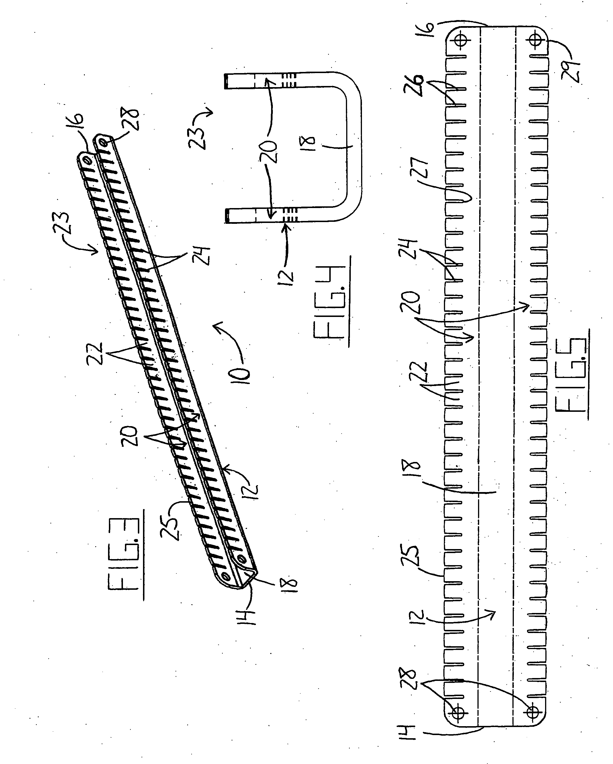
[0053] the overload indicator according to the present invention is shown in FIG. 3. The overload indicator 10 is made of a longitudinal member 12 having a U-shaped cross section as shown in FIG. 4. The U-shaped member 12 has a central portion 18 extending perpendicularly between parallel side portions 20. Between opposite ends 14 and 16, the longitudinal member 12 has a series of slots 24 extending from a side 23 opposite the central portion 18 toward the central portion 18 in each side portion 20. These slots 24 define teeth 22, each of which is positioned between two adjacent slots 24. At each of the ends 14 and 16, there is provided a pair of holes for mounting the overload indicator on an appropriate load supporting apparatus. A hole 28 is provided through each side portion 20 at each of the ends 14 and 16 for use as a connection point by means of which the overload indicator 10 can be installed for use in a load supporting apparatus.
[0054] The absence of material in the side p...
second embodiment
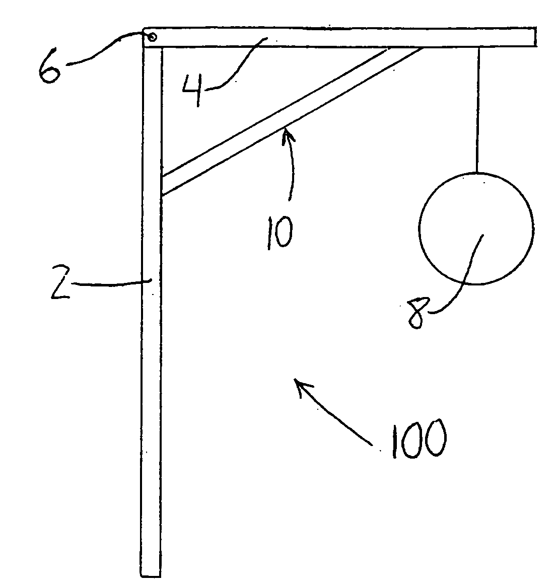
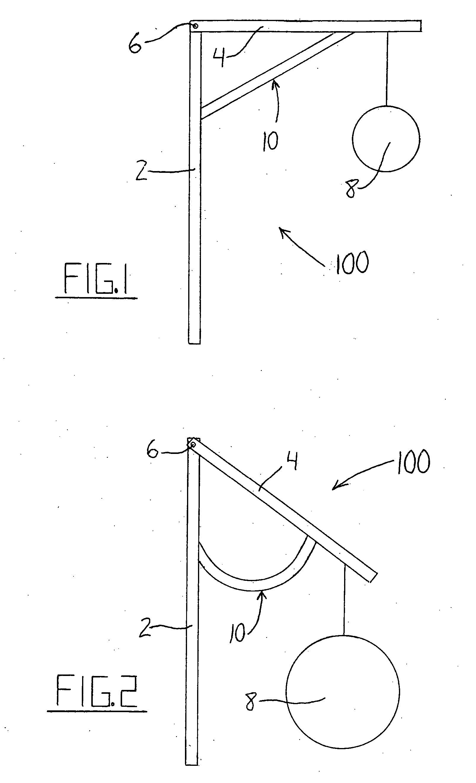
[0058]FIG. 7 illustrates the use of the present invention, generally indicated at 50, in an alternate mounting arrangement. A load supporting apparatus 200, similar to the one illustrated in FIGS. 1 and 2, features a first member 2 extending upward and having a second member 4 supported at the upper end and extending outward to one side. The two members are connected at an attachment point 6 featuring suitable fastening means that will resist moments of limited magnitude about that point. The alternate mounting arrangement for the overload indicator 50 consists of mounting elements 56 which support the overload indicator 50 between them. Each mounting element is angularly attached to one of the two members and extends toward the other mounting element. The element 56 on the first member 2 is attached at a point downward from the second member 4 while the element 56 on the second member is located between the load 8 and the first member 2. In this arrangement, the overload indicator ...
PUM
 Abstract
Description
Claims
Application Information
 - R&D
- Intellectual Property
- Life Sciences
- Materials
- Tech Scout
- Unparalleled Data Quality
- Higher Quality Content
- 60% Fewer Hallucinations
Browse by: Latest US Patents, China's latest patents, Technical Efficacy Thesaurus, Application Domain, Technology Topic, Popular Technical Reports.
© 2025 PatSnap. All rights reserved.Legal|Privacy policy|Modern Slavery Act Transparency Statement|Sitemap|About US| Contact US: help@patsnap.com


