Overload indicator for a load supporting apparatus

a technology for supporting apparatus and overload indicator, which is applied in the direction of apparatus for force/torque/work measurement, chemical indicators, instruments, etc., can solve the problems of injury and property damage, improper use of load supporting apparatus such as cranes, jibs, davits or fall protection systems,

Active Publication Date: 2008-04-29
D B IND
View PDF16 Cites 16 Cited by
  • Summary
  • Abstract
  • Description
  • Claims
  • Application Information

AI Technical Summary

Benefits of technology

[0009]the longitudinal member of the overload indicator being adapted to bend if the load exceeds the load limit of the apparatus such that the first distance between the opposite ends of said longitudinal member is decreased, thereby visually indicating overloading of the apparatus; and
[0010]the second member being arranged to move during bending of the longitudinal member of the overload indicator such that the second distance between the first and second connection points is decreased.
[0011]The overload indicator of the load supporting apparatus is arranged to bend during overloading of the apparatus, thereby visually indicating the overload to a user or observer. The indicator is arranged to extend between connection points on a first member and a second load supporting member of the apparatus in order to bend in response to excessive loading of the second member. The bending action moves the opposite ends of the member closer together, thereby reducing the distance between the connection points of the two members. This brings the load supported by the second member closer to the first member.
[0016]In the case where the second member extends out to one side of the upward extending first member and supports the load at a distance therealong, bringing the load closer to the first member reduces the moment about the attachment point of the two members. This reduces wear and the likelihood of failure of the apparatus, thereby preventing accidents and keeping maintenance costs down, as only the overload indicator will need replacement.
[0029]the slots of the overload indicator being arranged to cause the longitudinal member of said overload indicator to bend concavely with respect to the first side thereof during overloading of the apparatus such that the first distance between the opposite ends of said longitudinal member is decreased; and
[0030]the second member being arranged to move during bending of the longitudinal member of the overload indicator such that the second distance between the first and second reference points is decreased.

Problems solved by technology

The use of a load supporting apparatus such as a crane, jib, davit or fall protection system can be quite dangerous if used improperly.
Death, injury and property damage can result from attempting to lift a load that exceeds the recommended loading range for which a particular apparatus was designed.

Method used


Image

  • Overload indicator for a load supporting apparatus
  • Overload indicator for a load supporting apparatus
  • Overload indicator for a load supporting apparatus

Examples


first embodiment

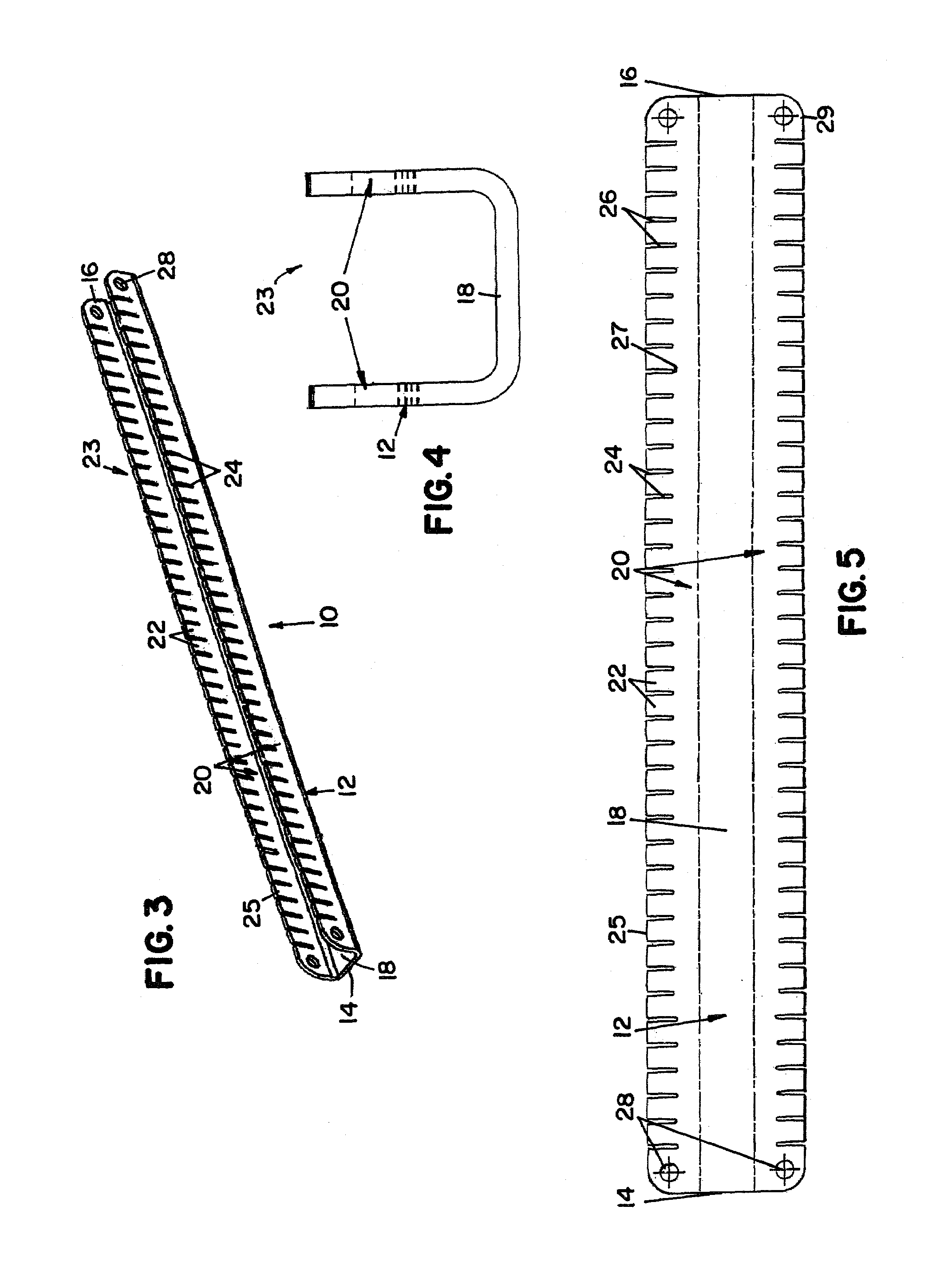
[0053]the overload indicator according to the present invention is shown in FIG. 3. The overload indicator 10 is made of a longitudinal member 12 having a U-shaped cross section as shown in FIG. 4. The U-shaped member 12 has a central portion 18 extending perpendicularly between parallel side portions 20. Between opposite ends 14 and 16, the longitudinal member 12 has a series of slots 24 extending from a side 23 opposite the central portion 18 toward the central portion 18 in each side portion 20. These slots 24 define teeth 22, each of which is positioned between two adjacent slots 24. At each of the ends 14 and 16, there is provided a pair of holes for mounting the overload indicator on an appropriate load supporting apparatus. A hole 28 is provided through each side portion 20 at each of the ends 14 and 16 for use as a connection point by means of which the overload indicator 10 can be installed for use in a load supporting apparatus.

[0054]The absence of material in the side por...

second embodiment

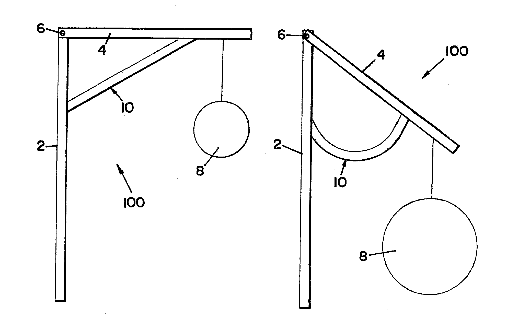
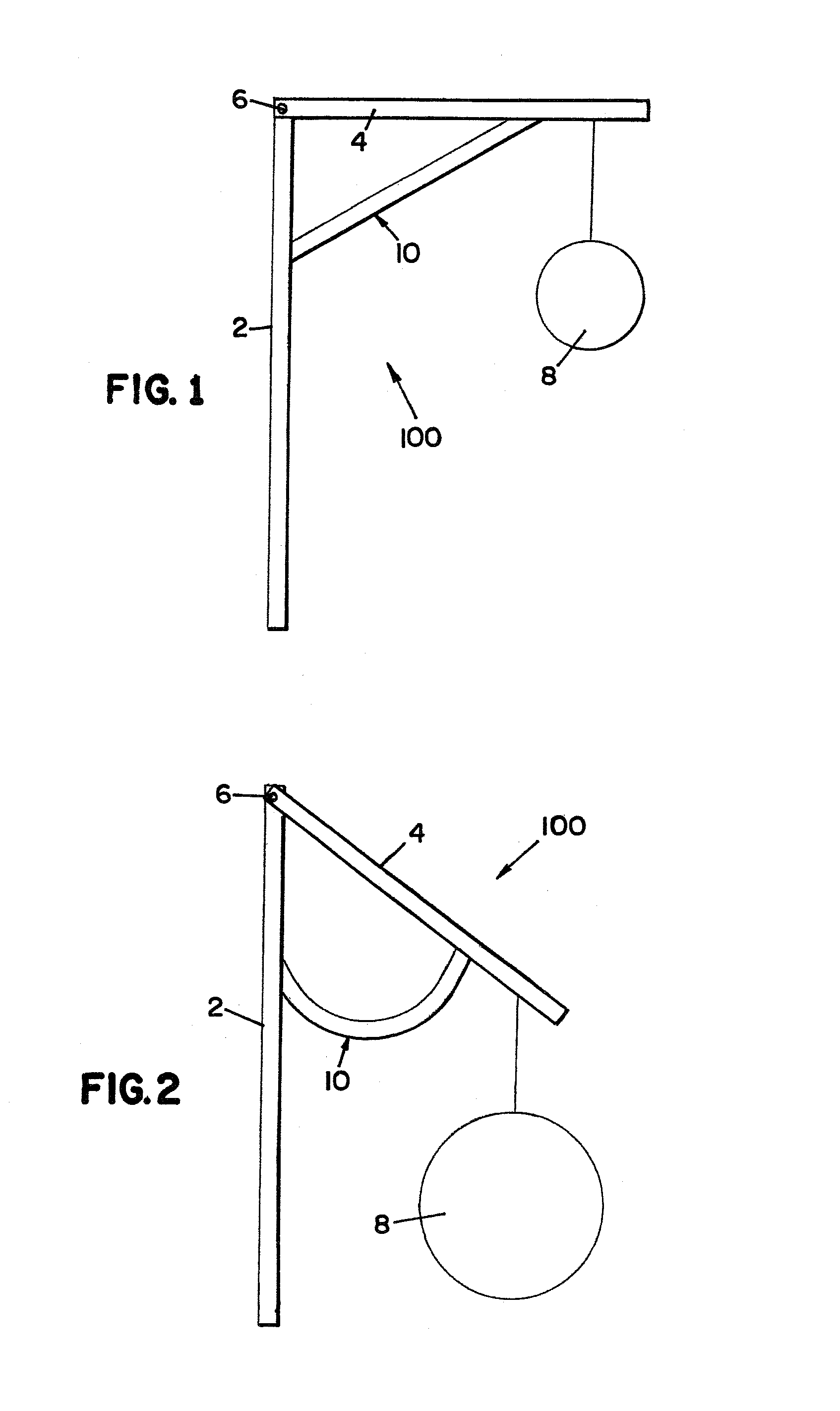
[0058]FIG. 7 illustrates the use of the present invention, generally indicated at 50, in an alternate mounting arrangement. A load supporting apparatus 200, similar to the one illustrated in FIGS. 1 and 2, features a first member 2 extending upward and having a second member 4 supported at the upper end and extending outward to one side. The two members are connected at an attachment point 6 featuring suitable fastening means that will resist moments of limited magnitude about that point. The alternate mounting arrangement for the overload indicator 50 consists of mounting elements 56 which support the overload indicator 50 between them. Each mounting element is angularly attached to one of the two members and extends toward the other mounting element. The element 56 on the first member 2 is attached at a point downward from the second member 4 while the element 56 on the second member is located between the load 8 and the first member 2. In this arrangement, the overload indicator ...


PUM

PropertyMeasurementUnit
angleaaaaaaaaaa
distanceaaaaaaaaaa
dimensionsaaaaaaaaaa

Abstract

An overload indicator for a load supporting apparatus is arranged to bend during overloading of the apparatus, thereby visually indicating the overload to a user or observer. The indicator features a longitudinal member having a U-shaped cross section defining one central and two side portions. A series of slots extend into each side portion from a side opposite the central portion such that the member will bend concavely with respect to that side, moving opposite ends of the member closer together. The indicator is arranged to extend between connection points on a first member and a second load supporting member of the apparatus in order to bend in response to excessive loading of the second member. The bending moves the connection points of the two members closer together, thus bringing the load closer to the first member.

Description

[0001]This invention relates to an overload indicator which visually indicates the overloading of a load supporting apparatus by means of bending at loads exceeding a predetermined limit.BACKGROUND OF THE INVENTION[0002]The use of a load supporting apparatus such as a crane, jib, davit or fall protection system can be quite dangerous if used improperly. Death, injury and property damage can result from attempting to lift a load that exceeds the recommended loading range for which a particular apparatus was designed. Concerns over safety therefore create a desire for a device that can prevent accidents by providing an indication to a user or observer when a load supporting apparatus is being overloaded. Provided with such a warning, the user can unload the apparatus immediately in order to avert failure and resulting casualties. For cases where the load cannot be removed quickly and safely, it is also desirable to have a means to reduce the effect of the overloading and prevent subst...

Claims


Application Information

Patent Timeline
Patent Type & Authority Patents(United States)
IPC IPC(8): G01L5/00
CPCB66C23/90G01L5/047Y10S116/34
Inventor VETESNIK, JAN
Owner D B IND
Why Eureka
Try Eureka