Rate-Controlled Optical Burst Switching

a technology of optical burst switching and rate control, applied in the field of data networks, can solve problems such as burst loss, burst loss, and latency and burst loss of burst transfer

Inactive Publication Date: 2007-05-24
RPX CLEARINGHOUSE
View PDF12 Cites 18 Cited by
  • Summary
  • Abstract
  • Description
  • Claims
  • Application Information

AI Technical Summary

Problems solved by technology

On the other hand, for a given nodal degree, scalability generally increases with the network diameter, but to the detriment of network efficiency.
Prior-art burst switching has attractive features but has two main drawbacks: burst-transfer latency and burst loss.
It is noted that even if a very long time gap is kept between a burst-transfer request and the data burst itself, the lack of buffers at the core node may result in burst loss and a significant idle time.
In the closed-loop scheme, the time delay involved in sending a burst transfer request and receiving an acceptance before sending a burst may be unacceptably high, leading to idle waiting periods and low network utilization in addition to requiring large storage at the edge nodes.
In the open-loop scheme, a burst may arrive at a core node before the optical switch can be configured to switch the burst and the burst may be lost.
Furthermore, the fact that the burst has been lost at the core node remains unknown to the source node for some time and a lost burst would have to be sent again after a predefined interval of time.
This renders closed-loop burst scheduling inappropriate.
The high round-trip delay requires that the source node have a sizeable buffer storage.
On the other hand, open-loop burst scheduling, which overcomes the delay problem, can result in substantial burst loss due to unresolved contention at the core nodes.
However, a burst has to wait at its source node for a period of time slightly exceeding a round-trip delay between the source node and a selected core node.

Method used


Image

  • Rate-Controlled Optical Burst Switching
  • Rate-Controlled Optical Burst Switching
  • Rate-Controlled Optical Burst Switching

Examples


Embodiment Construction

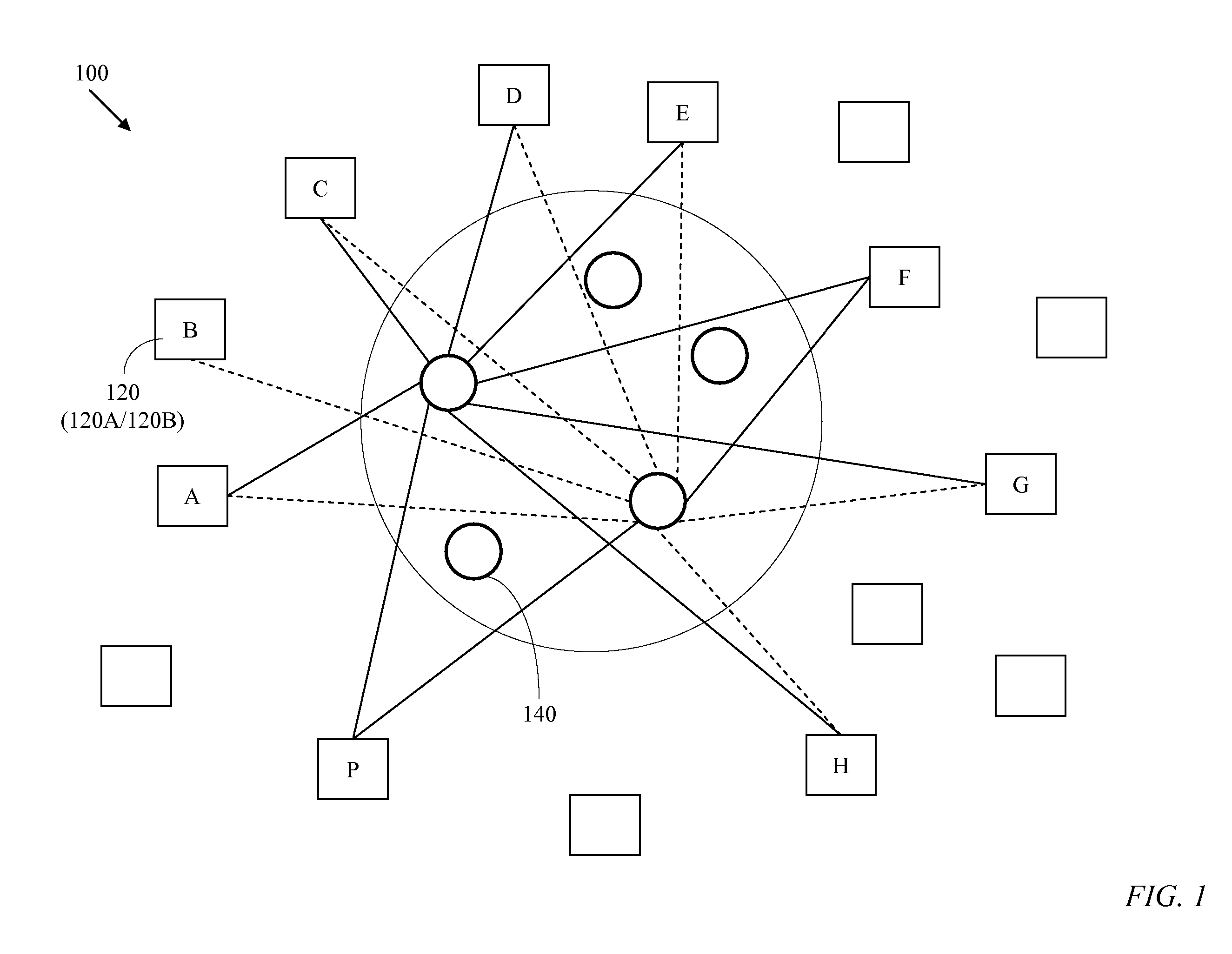
[0055] A star network's main attraction is its high performance and simplicity of control. However, it is suitable only for limited geographic or topological coverage. A composite star network 100, illustrated in FIG. 1, may be viewed as a superposition of several star networks which are merged only at the edge nodes 120 while the core nodes 140 can be widely distributed and independent. An edge node 120 comprises a source node 120A and an associated sink node 120-B. Hereinafter, reference to an edge node 120 also implies reference to the source node 120A and the sink node 120B that constitute the edge node 120. Similarly, reference to a source node 120A or a sink node 120B implies reference to the edge node 120 to which either belongs. The core nodes 140 of a composite-star network are not connected to each other. The composite-star network 100 retains the attractive properties of a star network while providing a wide geographic and topological coverage. The composite-star network ...


PUM


Abstract

A method and apparatus are provided for low latency loss-free burst switching. Burst schedules are initiated by controllers of bufferless core nodes and distributed to respective edge nodes. In a composite-star network, the burst schedules are initiated by any of a plurality of bufferless core nodes and distributed to respective edge nodes. Burst formation takes place at source nodes and a burst size is determined according to an allocated bitrate of a burst stream to which the burst belongs. An allocated bitrate of a burst stream may be modified according to observed usage of scheduled bursts of a burst stream. A method of control-burst exchange between each of a plurality of edge nodes and each of a plurality of bufferless core nodes enables burst scheduling, time coordination, and loss-free burst switching. Both the payload bursts and control bursts are carried by optical channels connecting the edge nodes and the core nodes. A method and a circuit are provided for generating burst descriptors wherein each burst is associated with a burst stream and each burst stream is allocated a service bitrate. The generated burst descriptors are used in each master controller in each core node to create the burst schedules. In a conventional burst-scheduling process, the burst queues at a master controller of an optical switch receives burst descriptors from the source nodes and schedules the burst switching times. In a distinct departure, according to the present invention the burst descriptors are generated by a master controller of an optical switch in a core node, the switching times of the corresponding bursts are scheduled, and the schedules are distributed to the respective edge nodes. The burst-descriptor generation is based on burst-stream bitrate-allocation defined by the source nodes.

Description

PRIOR APPLICATION [0001] This application is a continuation application of Ser. No. 10 / 054512, currently allowed.FIELD OF THE INVENTION [0002] The present invention relates to data networks and, in particular, to burst switching in an optical-core network. BACKGROUND OF THE INVENTION [0003] A data network comprises a number of source nodes, each source node receiving traffic from numerous traffic sources, and a number of sink nodes, each sink node delivering data to numerous traffic sinks. The source nodes can be connected to the sink nodes directly or through core nodes. Source nodes and sink nodes are often paired to form edge nodes, where a source node and sink node of an edge node share memory and control. [0004] Each link between two nodes may comprise multiple channels. An optical multi-channel link uses Wavelength Division Multiplexing (WDM). WDM allows a given optical link to be divided into multiple channels, where a distinct stream of data may be transmitted on each channe...

Claims


Application Information

Patent Timeline
Patent Type & Authority Applications(United States)
IPC IPC(8): H04L12/50H04Q11/00H04L47/724
CPCH04Q11/0066H04W28/0257H04Q2011/0083H04Q2011/0088H04L45/44H04L47/724H04W28/0252H04L47/783H04L47/781H04W74/004H04W74/006H04W74/002H04W72/14H04W72/1294H04W72/1289H04W72/1284H04W72/1278H04W72/1273H04W72/1268H04W72/1263H04W72/1257H04W72/1205H04W72/042H04W72/0413H04W72/0406H04W28/22H04W28/20H04W28/18H04W28/16H04Q2011/0064H04Q11/0005H04L47/39H04L47/527H04L47/628H04L47/28H04L49/3072H04L49/254H04Q2011/0016H04Q2011/0024H04Q2011/0039H04W72/23H04W72/535H04W72/12H04W72/20H04W72/21
Inventor BESHAI, MAGED E.JAMOUSSI, BILEL N.
Owner RPX CLEARINGHOUSE
Why Eureka
Try Eureka