
All-optical time slice switching method based on time synchronization

A technology of optical time slice switching and time synchronization, which is applied in the field of optical network communication, can solve problems such as inability to guarantee data transmission and limit the application of OBS technology, and achieve flexible sub-wavelength granularity all-optical switching and reliable sub-wavelength granularity all-optical switching Effect

Active Publication Date: 2014-02-12
TSINGHUA UNIV
View PDF3 Cites 10 Cited by
  • Summary
  • Abstract
  • Description
  • Claims
  • Application Information

AI Technical Summary

Problems solved by technology

However, just like OPS, due to packet loss, OBS cannot guarantee reliable data transmission, especially in the case of high business load, the packet loss rate of OBS will far exceed that of traditional packet switching technology when there is no buffer device, which severely limits Application of OBS Technology
[0004] It can be seen from the above that in the current all-optical switching network, there are some defects in the existing OCS technology, OPS technology or OBS technology, and there is no all-optical switching technology that can overcome these defects at the same time.

Method used


Image

  • All-optical time slice switching method based on time synchronization
  • All-optical time slice switching method based on time synchronization
  • All-optical time slice switching method based on time synchronization

Examples


Embodiment Construction

[0026] Embodiments of the present invention are described in detail below, examples of which are shown in the drawings, wherein the same or similar reference numerals designate the same or similar elements or elements having the same or similar functions throughout. The embodiments described below by referring to the figures are exemplary and are intended to explain the present invention and should not be construed as limiting the present invention.

[0027] The all-optical chip switching method based on time synchronization according to the embodiment of the present invention comprises the following steps:

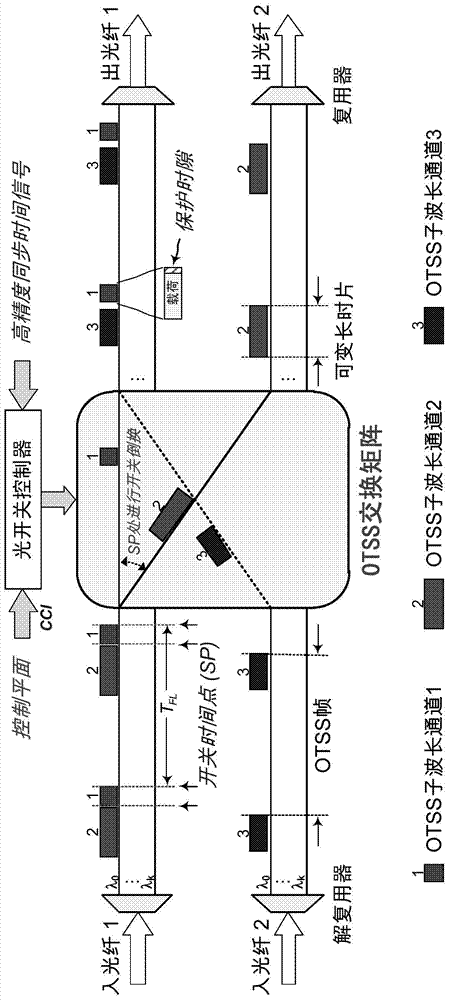
[0028]A. In a single-wavelength or multi-wavelength optical network, each wavelength link supporting all-optical time slice switching transmits data through periodically repeated OTSS (Optical Time Slice Switching) frames in the time domain. Wherein, each OTSS frame includes any number of variable-length time slices, and guard time slots are set between each time slice. ...


PUM


Abstract

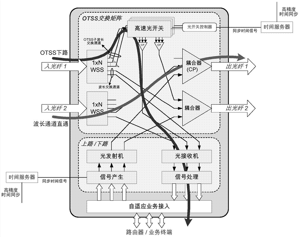
The invention discloses an all-optical time slice switching method based on time synchronization. According to the method, continuous service data streams in an optical network are assembled to periodically-repeated optical time slices in a segmented mode in a time domain and are transferred in an asynchronous transfer mode. Network nodes obtain high precision synchronization time through whole network time, an optical switch is controlled to switch optical time slices reaching at precise time points periodically to a target port, and therefore full optical switching is completed. When a connection request reaches, available routes, wavelengths and occupation time slots are calculated through source nodes according to network available time slot resource information, and are reserved through a connection management module. After resource reservation is finished, the source nodes send out optical time slices of bearer service periodically at reserved time slots. Destination nodes restore received optical time slices to original service steams. Compared with an existing switching technology, the all-optical time slice switching method has the remarkable advantages that reliable and flexible sub-wavelength granularity all-optical switching can be achieved without participation of all-optical caches and all-optical logic devices.

Description

technical field [0001] The invention belongs to the technical field of optical network communication, and in particular relates to an all-optical time slice switching method based on time synchronization. Background technique [0002] With the rapid increase in the amount of network data exchange, the node size, cost and energy consumption of the electrical packet switching network are facing a huge test, and the final network capacity will be limited by the bandwidth bottleneck of the router. Introducing all-optical switching is an effective way to break through this bottleneck. [0003] However, the existing all-optical circuit switching (OCS) technology can only provide wavelength-level large-grained data exchange, and the utilization rate of network bandwidth is very low. All-optical packet switching (OPS) technology can provide ultra-fine sub-wavelength granular switching, but it requires the participation of all-optical cache and all-optical logic devices. These devi...

Claims


Application Information

Patent Timeline
Patent Type & Authority Applications(China)
IPC IPC(8): H04J3/06H04Q11/00H04L12/721
CPCH04Q11/0066H04J14/083H04Q11/0005H04Q2011/0039H04Q2011/0045H04J14/08H04L7/0041H04L7/0075H04Q2011/0033
Inventor 华楠郑小平张汉一周炳琨
Owner TSINGHUA UNIV
Learn More